Eureka AIR delivers breakthrough ideas for toughest innovation challenges, trusted by R&D personnel around the world.

Optical cavity enhanced turbidimeter and turbidity measuring method

a technology of optical cavity and turbidimeter, which is applied in the direction of instruments, suspensions and porous materials analysis, material analysis, etc., can solve the problem of difficult to measure the turbidity of the solution

Inactive Publication Date: 2010-11-25
ELECTRONICS & TELECOMM RES INST
View PDF6 Cites 15 Cited by
  • Summary
  • Abstract
  • Description
  • Claims
  • Application Information

AI Technical Summary

Benefits of technology

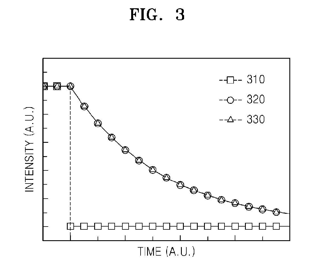
[0013]According to the optical cavity enhanced turbidimeter of the present invention, the turbidity of a sample solution can be precisely measured by disposing the vessel containing the sample solution within the optical cavity, and measuring the attenuation rate of a beam having a pulse profile or steep intensity gradient after the beam is transmitted through the optical cavity. Therefore, although a small amount of a sample solution is used, the turbidity of the sample solution can be precisely measured.

Problems solved by technology

That is, since a scattering of the beam is measured while the beam passes through the solution once, it is difficult to measure the turbidity of the solution when the amount of the solution is not sufficiently large or the particle concentration of the solution is low.

Method used


Image

  • Optical cavity enhanced turbidimeter and turbidity measuring method
  • Optical cavity enhanced turbidimeter and turbidity measuring method
  • Optical cavity enhanced turbidimeter and turbidity measuring method

Examples


Embodiment Construction

[0020]The present invention will now be described more fully with reference to the accompanying drawings, in which exemplary embodiments of the invention are shown.

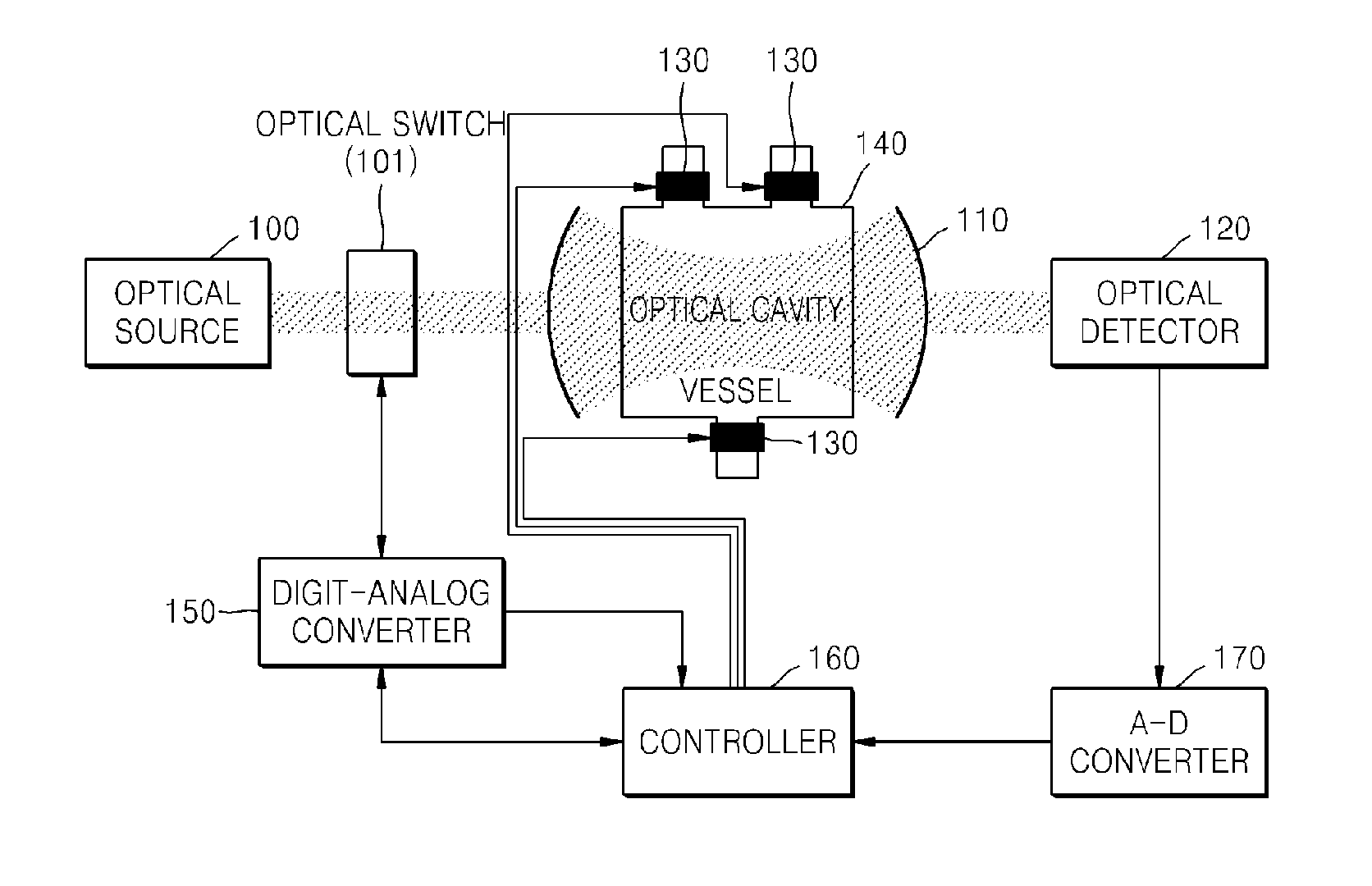
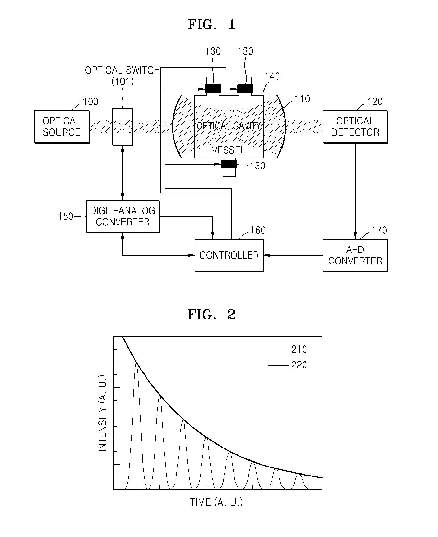
[0021]FIG. 1 illustrates an optical cavity enhanced turbidimeter according to an embodiment of the present invention.

[0022]Referring to FIG. 1, an optical source 100 may include a component emitting white light and a filter transmitting light having a specific wavelength. Alternatively, the optical source 100 can be a laser.

[0023]An optical switch 101 controls white light or laser light emitted from the optical source 100. The optical switch 101 operates based on optical switching effects such as an electro-optic effect or an acousto-optic effect so as to vary the intensity of light emitted from the optical source 100 by converting the light into pulse light or suddenly blocking the light.

[0024]When a pulse laser is used as the optical source 100, optical switching is possible by using the optical source 100.

[0025]An opti...


PUM


Abstract

Provided are an optical cavity enhanced turbidimeter and a turbidity measure method. After casting a pulse beam or a beam having a steep intensity gradient into an optical cavity, the turbidity of the inside region of the optical cavity can be calculated using an attenuation rate of an output beam from the optical cavity.

Description

TECHNICAL FIELD[0001]The present invention relates to an optical cavity enhanced turbidimeter and a turbidity measuring method, and more particularly, to a method of measuring turbidity using an optical cavity including two highly reflective mirrors disposed to face each other so as to compare an attenuation rate of a beam output from the optical cavity with an input beam having a pulse profile or steep intensity gradient.[0002]The present invention has been derived from a research conducted for information technology (IT) development as supported by the Ministry of Information and Communication and Institute for Information Technology Advancement, Republic of Korea (Project management No.: 2006-S-007-02, Project title: ubiquitous-healthcare module system).BACKGROUND ART[0003]Turbidity is an optical property of fluids, and is proportional to the amount of particles that are suspended in the fluid to scatter light passing through the fluid.[0004]For example, in environmental tests su...

Claims


Application Information

Patent Timeline
IPC IPC(8): G01N21/00
CPCG01N15/06G01N2015/0693G01N21/534G01N15/075G01N15/00G01N15/14G01N21/00
Inventor HONG, JONG-CHEOLSUNG, GUN YONGPARK, SUN-HEEKIM, KYUNG-HYUNHUH, CHULKO, HYUN-SUNGKIM, WAN-JOONG
Owner ELECTRONICS & TELECOMM RES INST
Why Eureka
Eureka Blog
Learn More