Radio communication device and response signal diffusion method

a technology of radio communication and response signal, applied in the direction of multiplex communication, orthogonal multiplex, wireless commuication services, etc., to achieve the effect of suppressing inter-code interferen

Active Publication Date: 2010-11-25
OPTIS WIRELESS TECH LLC
View PDF4 Cites 10 Cited by
  • Summary
  • Abstract
  • Description
  • Claims
  • Application Information

AI Technical Summary

Benefits of technology

[0017]The present invention can suppress inter-code interference between an ACK / NACK signal and a CQI signal that are code-multiplexed.

Problems solved by technology

However, due to an influence of transmission timing difference in mobile station, multipath delayed waves, frequency offset, and so forth, a plurality of ACK / NACK signals and CQI signals from a plurality of mobile stations do not necessarily reach a base station at the same time.

Method used


Image

  • Radio communication device and response signal diffusion method
  • Radio communication device and response signal diffusion method
  • Radio communication device and response signal diffusion method

Examples


embodiment 1

[0036]The configuration of base station 100 according to Embodiment 1 of the present invention is shown in FIG. 8, and the configuration of mobile station 200 according to Embodiment 1 of the present invention is shown in FIG. 9.

[0037]To prevent the description from becoming complex, FIG. 8 shows components relating to the transmission of downlink data and uplink reception of an ACK / NACK signal corresponding to that downlink data, closely related to the present invention, while components relating to the reception of uplink data are omitted from the drawing and the description. Similarly, FIG. 9 shows components relating to the reception of downlink data, and uplink transmission of an ACK / NACK signal corresponding to that downlink data, closely related to the present invention, while components relating to the transmission of uplink data are omitted from the drawing and the description.

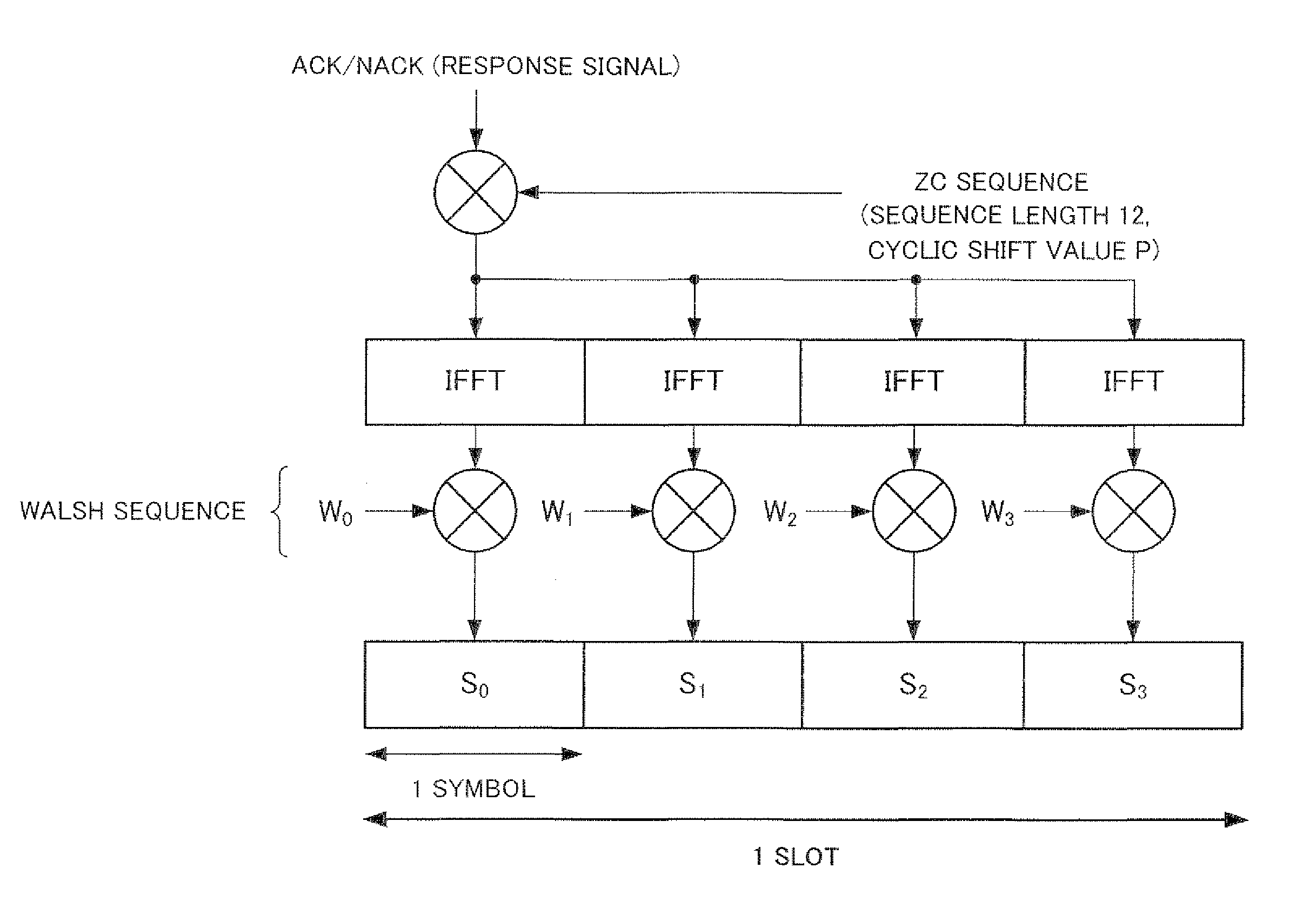
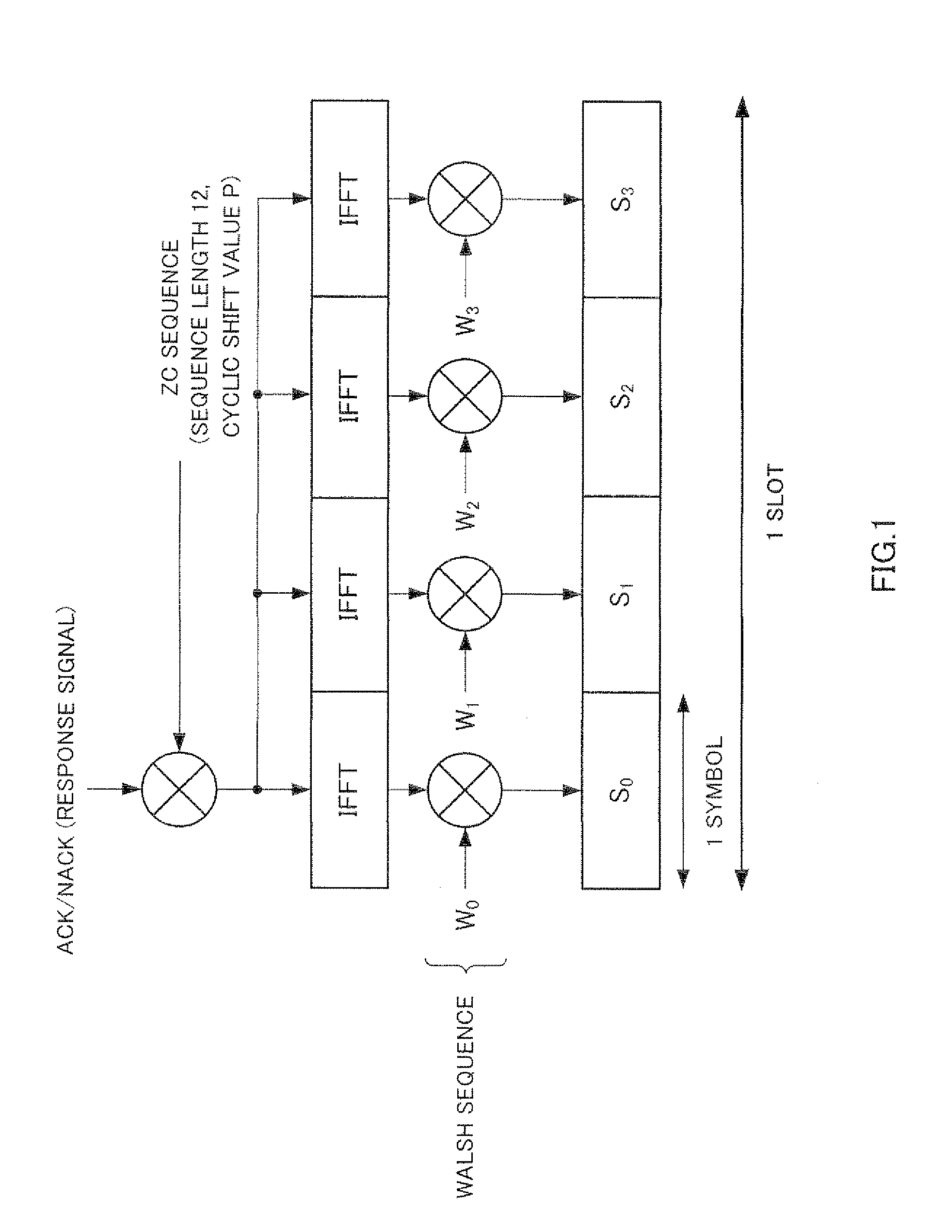
[0038]In the following description, a case is described in which a ZC sequence is used for first s...

embodiment 2

[0081]A base station and mobile station according to Embodiment 2 of the present invention have the same kind of configurations as a base station (see base station 100 in FIG. 8) and mobile station (see mobile station 200 in FIG. 9) according to Embodiment 1, and differ only in regard to part of the processing performed by the control channel allocation section (control channel allocation section 102 shown in FIG. 8).

[0082]FIG. 12 is a drawing showing CCEs corresponding to PUCCHs used by mobile stations, which are referenced by a control channel allocation section according to this embodiment. FIG. 12 is basically similar to FIG. 10, and therefore only points of difference will be described here.

[0083]As shown in FIG. 12, a base station according to this embodiment employs adjacent CCEs #3 and #15 following a cyclic shift value including a smaller number of CCEs for ACK / NACK use among cyclic shift values including CCEs for ACK / NACK use as CCEs for CQI use. By this means, the number ...

embodiment 3

[0086]In Embodiment 3 of the present invention, control channel allocation will be described for a case in which a cyclic shift interval between PUCCHs used by mobile stations is 3 or more.

[0087]A base station and mobile station according to Embodiment 3 have the same kind of configurations as a base station (see base station 100 in FIG. 8) and mobile station (see mobile station 200 in FIG. 9) according to Embodiment 1, and differ only in regard to part of the processing performed by the control channel allocation section (control channel allocation section 102 shown in FIG. 8),

[0088]FIG. 14 is a drawing showing CCEs corresponding to PUCCHs used by mobile stations, which are referenced by a control channel allocation section according to this embodiment. FIG. 14 is basically similar to FIG. 10, and therefore only points of difference will be described here.

[0089]As shown in FIG. 14, a base station according to this embodiment employs CCEs #2 and #10 as CCEs for CQI use, and makes CC...


PUM


Abstract

Provided is a radio communication device which can suppress inter-code interference between an ACK / NACK signal and a CQI signal which are code-multiplexed. In this device, a diffusion unit (214) diffuses the ACK / NACK signal inputted from a judgment unit (208) by using a ZC sequence. A diffusion unit (219) diffuses the CQI signal by using a cyclic shift ZC sequence. By using a Walsh sequence, a diffusion unit (216) further diffuses the ACK / NACK signal which has been diffused by using the ZC sequence. A control unit (209) controls the diffusion unit (214), the diffusion unit (216), and the diffusion unit (219) so that the minimum value of the difference between the CQI signals from a plurality of mobile stations and a cyclic shift amount of the ACK / NACK signal is not smaller than the minimum value of the difference between the cyclic shift amounts of the ACK / NACK signals from the plurality of mobile stations.

Description

[0001]This is a continuation of application number 12 / 600,835 filed Nov. 18, 2009, which is a 371 application of PCT / JP2008 / 002199 filed Aug. 12, 2008, which is based on Japanese Application No. 2007-211102 filed Aug. 13, 2007, the entire contents of each of which are incorporated by reference herein.TECHNICAL FIELD[0002]The present invention relates to a radio communication apparatus and response signal spreading method.BACKGROUND ART[0003]In mobile communications, ARQ (Automatic Repeat Request) is applied to downlink data from a radio communication base station apparatus (hereinafter abbreviated to “base station”) to a radio communication mobile station apparatus (hereinafter abbreviated to “mobile station”). That is to say, a mobile station feeds back a response signal representing error detection results of downlink data, to the base station. A mobile station performs a CRC (Cyclic Redundancy Check) on downlink data, and, if CRC=OK is found (no error), feed back an ACK (ACKnowle...

Claims


Application Information

Patent Timeline
Patent Type & Authority Applications(United States)
IPC IPC(8): H04W40/00H04B1/707H04B1/7097H04J11/00H04J13/00H04W24/02H04W24/10H04W72/04
CPCH04J13/0062H04J13/0074H04L1/1671H04W72/0413H04L25/03828H04L2001/125H04L5/0016H04B1/7097H04L1/18H04B1/707H04J11/00H04W72/21H04W72/23H04W72/54H04B1/7103H04J13/102H04J13/18H04L5/0055H04L5/0057H04W72/0446H04W88/02H04W88/08H04B7/0626H04L1/0026
Inventor FUTAGI, SADAKINAKAO, SEIGOIMAMURA, DAICHI
Owner OPTIS WIRELESS TECH LLC
Why Eureka
Try Eureka