
Apparatus for processing an audio signal and method thereof

a technology for audio signals and apparatuses, applied in the direction of volume compression/expansion, volume compression/expansion in untuned/low-frequency amplifiers, instruments, etc., can solve the problems of signal distortion, unintentional difference in the loudness of the sound actually falling on human ears,

Inactive Publication Date: 2010-11-25
LG ELECTRONICS INC
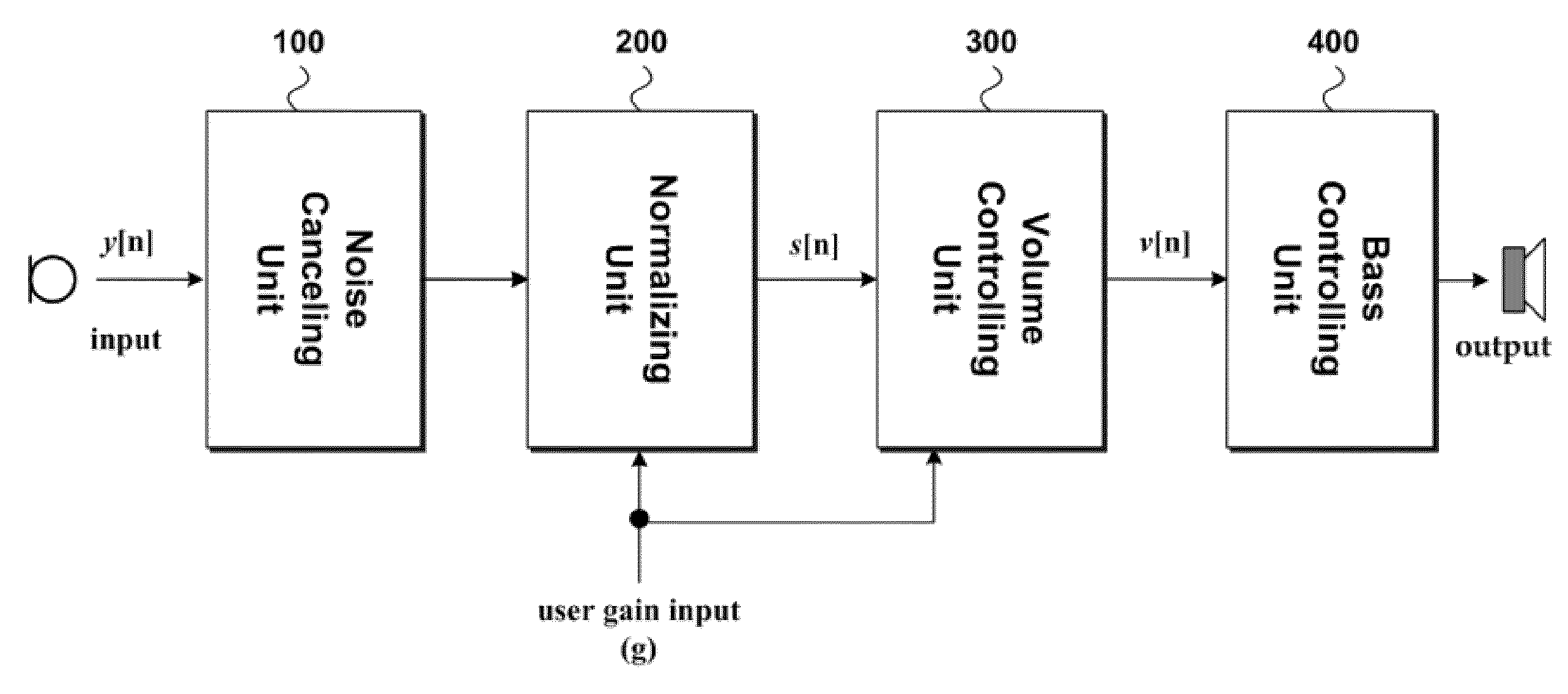
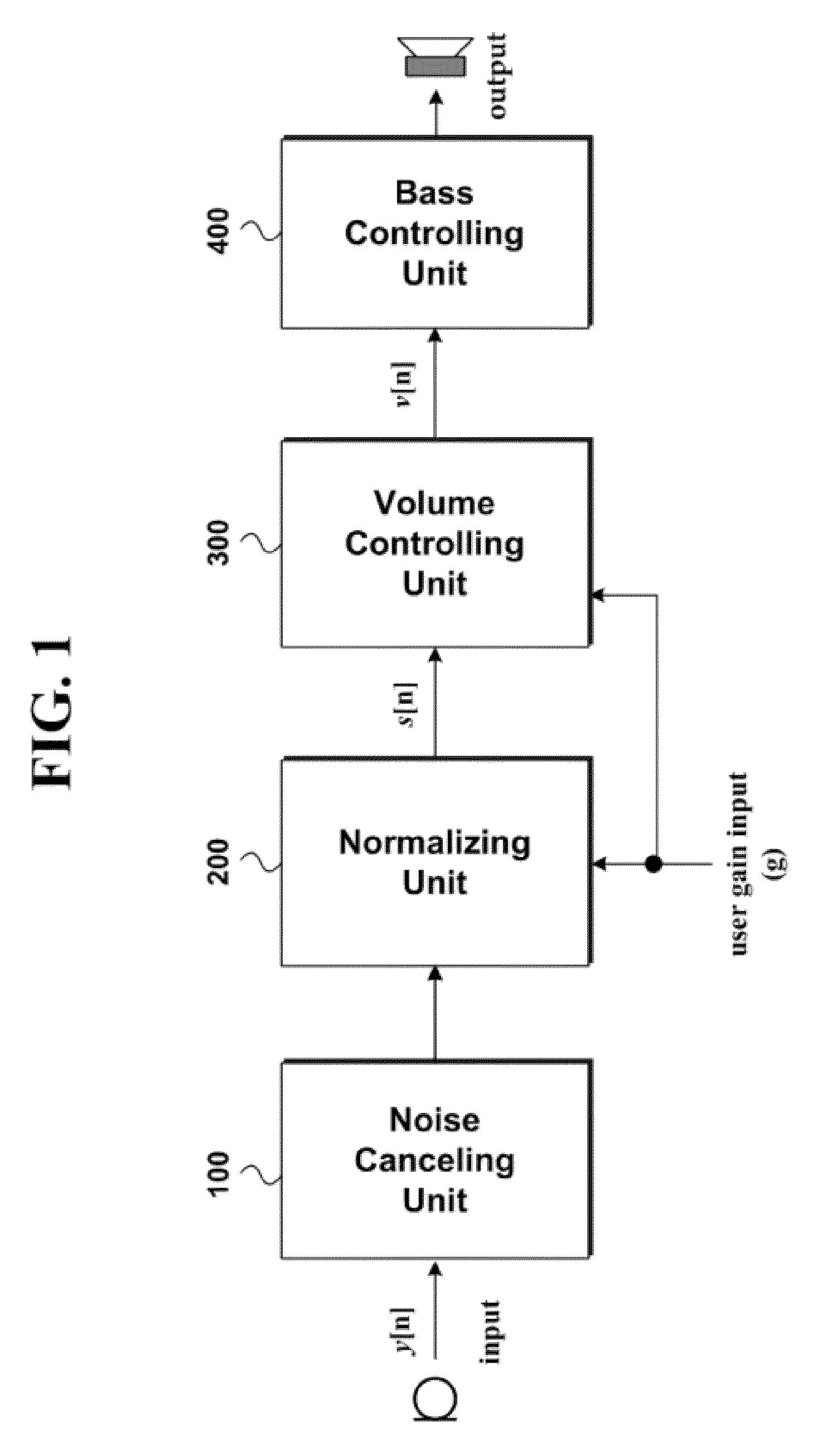
View PDF17 Cites 13 Cited by
  • Summary
  • Abstract
  • Description
  • Claims
  • Application Information

AI Technical Summary

Benefits of technology

[0009]An object of the present invention is to provide an apparatus for processing an audio signal and method thereof, by which a volume can be controlled using loudness of sound actually audible to a human for each sound pressure level.
[0012]A further object of the present invention is to provide an apparatus for processing an audio signal and method thereof, by which an adaptive filter can be applied to improve a bass if a frequency response of a loudspeaker is low.

Problems solved by technology

Since sound intensity based on a sound pressure level is considered in performing the volume control, it may cause a problem that loudness of the sound actually falling on human ears makes a difference unintentionally.
Moreover, in performing the bass control, if a frequency response of a loud speaker is low for a low frequency or bass is excessively boosted, it may cause a problem that a signal is distorted.

Method used


Image

  • Apparatus for processing an audio signal and method thereof
  • Apparatus for processing an audio signal and method thereof
  • Apparatus for processing an audio signal and method thereof

Examples


first embodiment

[0109]First of all, the user gain receiving part 322B receives a user gain input g like the former component of the same name in the first embodiment [S210].

[0110]Likewise, the comparing part 32B receives a user gain g and a low reference value glow [S220] and then determines whether the user gain g is greater than the low reference value glow [S240]. If the user gain g is smaller than the low reference value glow, the comparing part 324B delivers the low reference value glow to the non-linear gain generating part 326B and also delivers the user gain g and the low reference value glow to the linear gain generating part 328B. If the user gain g is greater than the low reference value glow, the comparing part 324B delivers the user gain g to the non-linear gain generating part 326B only.

[0111]A method of generating a non-linear gain and a linear gain per interval is explained with reference to FIG. 9 and FIG. 10 as follows.

[0112]Referring to FIG. 9 and FIG. 10, if the user gain g is e...

second embodiment

[0114]One example of generating the non-linear gain and the linear gain is represented as Formula 5.

If g>glow, g1=g, g2=1.0

If glow, g1=glow, g2=g / glow  [Formula 6]

[0115]In Formula 6, the g indicates a user gain input, the glow indicates a low reference value, the g1 indicates a non-linear gain, and the g2 indicates a linear gain.

[0116]FIG. 10 is a diagram for per-interval variations of linear and non-linear gains according to the second embodiment.

[0117]In a first case of Formula 6 (‘interval 2’ in FIG. 10), a user gain is a non-linear gain and a linear gain is set to 1. Hence, a volume control is non-linearly performed in this interval. In a second case of Formula 6 (‘interval 1’ in FIG. 10), a non-linear gain is a constant (e.g., glow) and a linear gain is able to increase according to a size of a user gain g. Hence, it can be observed that a linear control is relatively dominant in this interval.

[0118]The non-linear gain factor g1 and the linear gain factor g2 are generated base...


PUM


Abstract

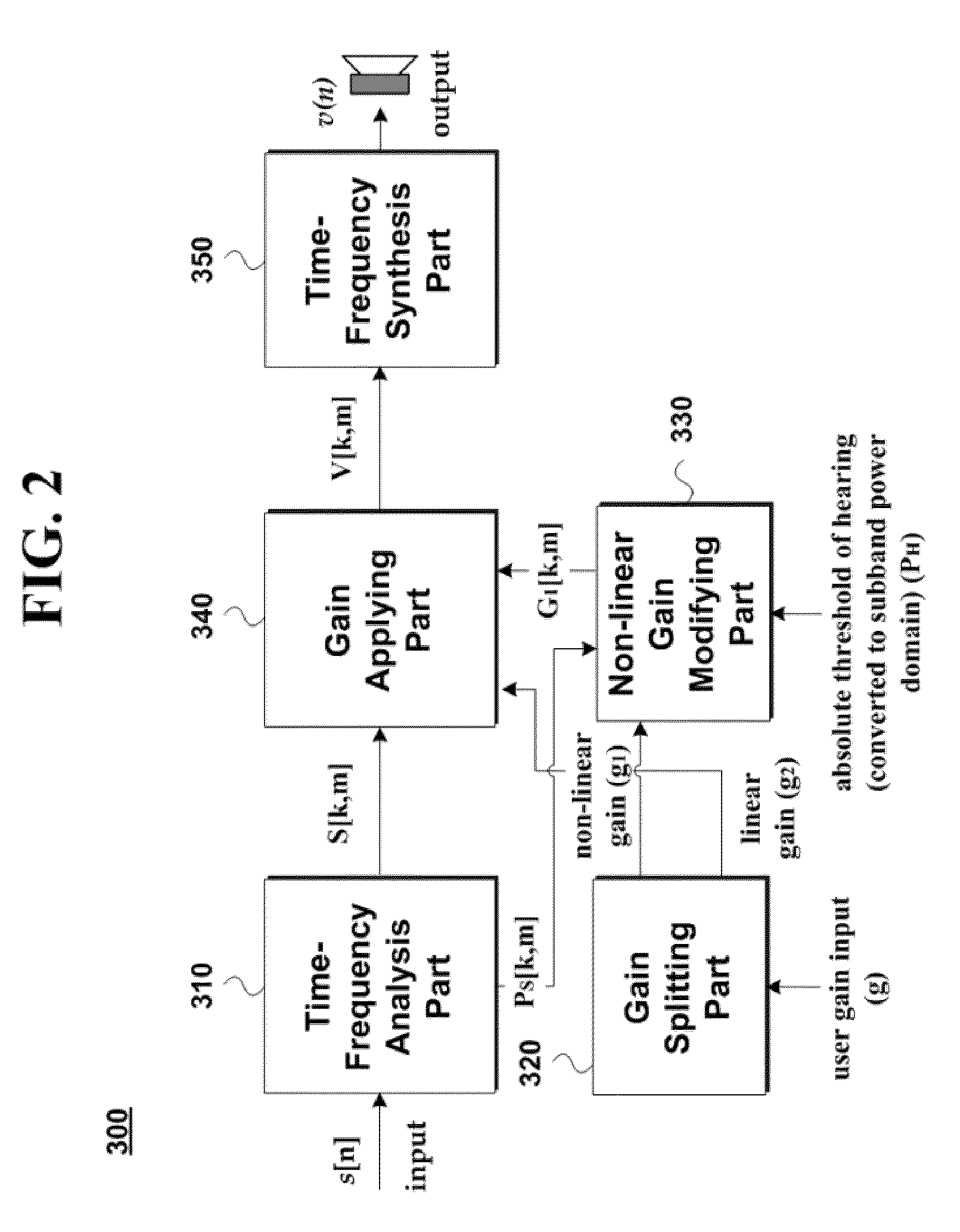
A method of processing an audio signal is disclosed. The present invention includes receiving, by an audio processing apparatus, an input signal; receiving user gain input; generating a linear gain factor and a non-linear gain factor using the user gain input; modifying the non-linear gain factor using absolute threshold of hearing and power of the input signal to generate a modified non-linear gain factor; and, applying the linear gain factor and the modified non-linear gain factor to the audio signal.

Description

CROSS-REFERENCE TO RELATED APPLICATION[0001]This application claims the benefit of U.S. Provisional Application No. 61 / 158,388 filed on Mar. 8, 2009 and U.S. Provisional Application No. 61 / 164,459, filed on Mar. 29, 2009, which are hereby incorporated by reference.BACKGROUND OF THE INVENTION[0002]1. Field of the Invention[0003]The present invention relates to an apparatus for processing an audio signal and method thereof. Although the present invention is suitable for a wide scope of applications, it is particularly suitable for processing an audio signal.[0004]2. Discussion of the Related Art[0005]Generally, an audio signal is outputted via a loud speaker provided to a television set, a portable device or the like or a headset and the like. Before the audio signal is outputted via a speaker or the like, an audio processor can perform such processing as noise canceling, normalizing, volume adjusting and the like on the audio signal.[0006]However, according to a related art, such pro...

Claims


Application Information

Patent Timeline
Patent Type & Authority Applications(United States)
IPC IPC(8): H03G3/02
CPCH03G9/005H03G9/025G10K11/1784G10K11/1788H03G7/002H03G1/02H03G3/001H03G5/165G10L21/0208
Inventor OH, HYEN-OFAVROT, ALEXISFALLER, CHRISTOFLEE, MYUNG HOONMOON, JONG HA
Owner LG ELECTRONICS INC
Learn More