Fixation clamp

a clamping and fixing technology, applied in the field of fixing clamps, can solve the problems of pins or rods, bulky fixing systems, etc., and achieve the effects of avoiding mismatching of components, avoiding insufficient connection strength, and fast and reliable operation

Active Publication Date: 2010-11-25
STRYKER EURO OPERATIONS HLDG LLC
View PDF5 Cites 81 Cited by
  • Summary
  • Abstract
  • Description
  • Claims
  • Application Information

AI Technical Summary

Benefits of technology

[0013]The clamp according to the invention allows readily treating different types of fractures or connecting bones of different sizes to each other, since usually different pin diameters are required. The clamp provides a plurality of different couplings possibilities which is an advantage, avoiding mismatching of components, which can lead to insufficient connecting strength. The clamp according to the invention also allows for clicking in rods from the side. The clamp can be built based on the usual metallic components and can comprise non-magnetic and non conductive materials, which are safe for temporary exposition in a MRI scanner, and can furthermore comprise plastic or composite materials or have electrical insulating cover surfaces.
[0014]It is an advantage of the clamp according to the invention that after having clamped a bone screw with one clamping assembly, a practitioner attaching subsequently a rod of an external fixator to the other clamping assembly can check the robustness of the external fixator, and if the practitioner finds that the rod used is not stiff enough, one simply opens the other clamping assembly, removes the thinner rod, turns the other clamping assembly e.g. 60 degrees into one direction or the other around the longitudinal axis to align a larger reception cavity with the new thicker rod and replaces said rod. This change does not necessitate the replacement of the clamp itself and is thus faster and more reliable since the clamping of the bone screw is not changed, and the use of a second sterile clamp at said time is avoided.

Problems solved by technology

U.S. Patent Publication No. 20060287652 discloses that the usual fixation clamps as e.g. known from U.S. Pat. No. 6,080,153 allow clamping of one single screw or pin to the frame and that this way to attach pins or rods leads to bulky fixation systems.

Method used


Image

  • Fixation clamp
  • Fixation clamp
  • Fixation clamp

Examples


first embodiment

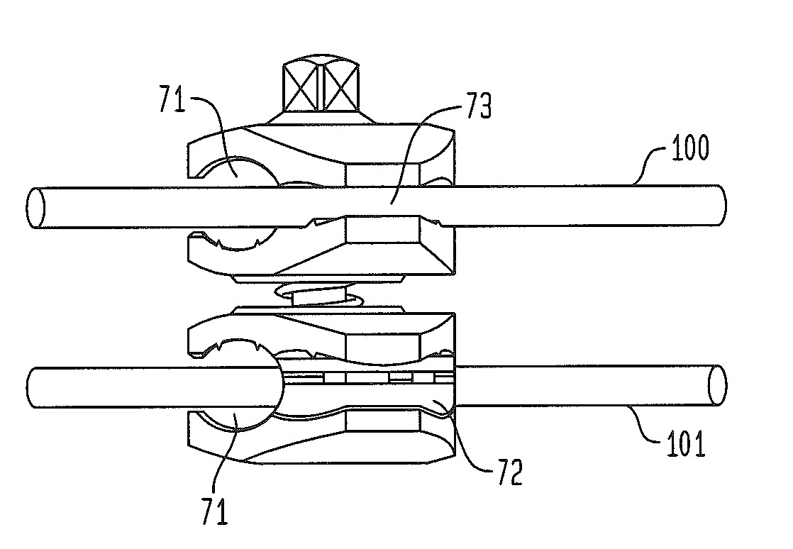
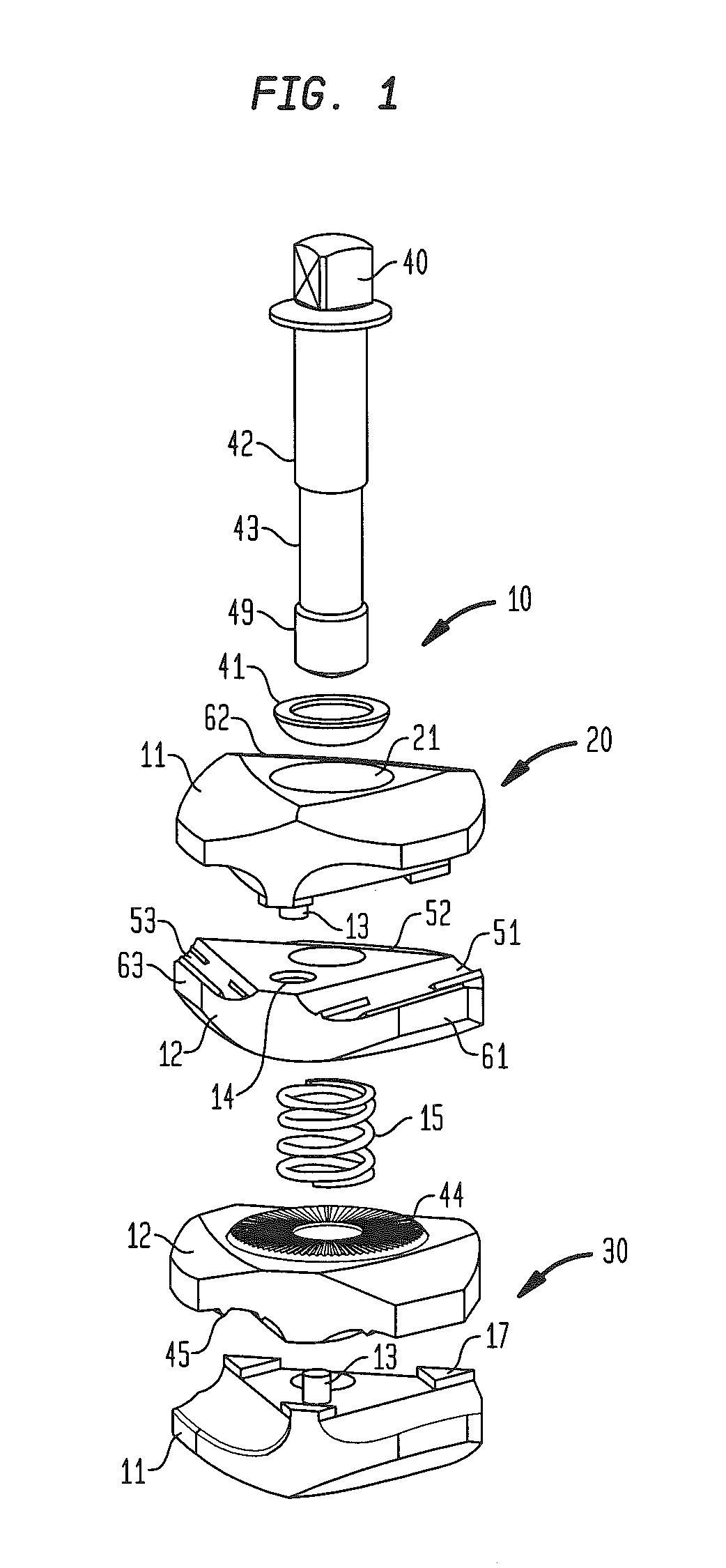
[0029]Referring to FIG. 1 there is shown a perspective exploded view of a preferred first embodiment of a clamp 10 pursuant to the invention. The clamp 10 consists of a first clamping assembly 20 and a second clamping assembly 30 and a shaft 40 which is positioned through bores 21, 31 within the two clamp assemblies 20, 30 along the longitudinal axis of shaft 40. Each clamping assembly has a first jaw 11 and a second jaw 12. Shaft 40 is preferably a locking element adapted to allow the closing the clamp assemblies 20 and 30. Shaft 40 enters a first jaw 11 through a washer 41. Washer 41 may have a part-spherical shape for receipt on a part-spherical surface of bore 21. The shaft 40 comprises a proximal portion 42 and a reduced diameter portion 43 which is followed by a threaded portion 49. The outer threaded portion 49 is adapted to be screwed into a complementary inner thread which may be formed within the distal most jaw 11 (bottom jaw of FIG. 1) so that turning the head of the sha...

second embodiment

[0051]FIG. 8 shows an exploded view of a clamp 10a of the present invention; FIG. 9 shows a top view of the clamp and FIG. 10 shows a cross-section of the clamp along line X-X in FIG. 9. The sequence of sizes for the first clamping assembly 20a is 13.5 mm, 8 mm and 5 mm. The choice of this sequence depends on the intended application (e.g. which limb is to be treated) of the external fixator set and follows the needs of the application.

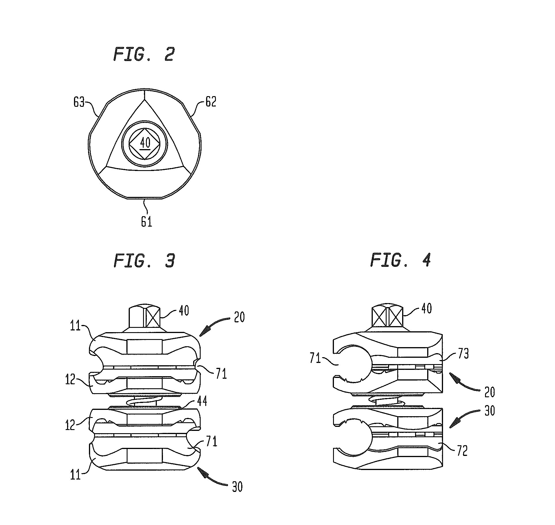
[0052]The clamping assemblies 20a, 30a of the embodiment have a triangular form, as can be seen from FIG. 9, having defined straight side walls 61, 62 and 63 and identically curved transitory portions. For a description of features which are identical to the clamp of FIG. 1 reference is made to that description.

[0053]Instead of spacers 17 in the corners of the plane surface of the jaws 11a there are provided two flattened semi-spherical spacers 27 on the surface. As mentioned above, the first clamping assembly 20a comprises a sequence of larger sized ...


PUM


Abstract

A fixation clamp for use in an external fixation system for holding bone fragments adjacent to each other with the help of fixation elements has at least one clamping assembly having a pair of jaws with at least two different size grooves to accommodate a bone fixation element such as a pin or rod. An alternate clamping assembly has at least three grooves wherein at least two of the grooves have a different size adapted to accommodate a correspondingly sized bone fixation element such as a bone pin. The longitudinal axes of the grooves define a polygon. The jaw pairs can be rotated about a central longitudinal axis to present different size reception cavities towards the pins or rocks depending on their diameter.

Description

CROSS REFERENCE TO RELATED APPLICATION[0001]The present application claims the benefit of European Patent Application No. 09160445.4, filed May 15, 2009, entitled Fixation Clamp, the disclosure of which is hereby incorporated herein by reference.BACKGROUND OF THE INVENTION[0002]The present invention relates to a fixation clamp and, more particularly, to a fixation clamp for use in an external fixation system for holding bone fragments adjacent to each other.[0003]External fixation systems are widely used to connect two or more bone fragments to each other. Such systems comprise bone screws, pins, wires which are inserted directly into the bone material and these systems use external structural elements as fixation rods, bars and rings. In order to connect the rods and bars to form a rigid frame, fixation clamps are used. Furthermore, fixation clamps are used to connect this screws and pins to the rigid frame to specifically hold bone fragments at an intended place.[0004]One adjustab...

Claims


Application Information

Patent Timeline
Patent Type & Authority Applications(United States)
IPC IPC(8): A61B17/00
CPCA61B17/6466F16B7/0493F16B2/12A61B17/666
Inventor CREMER, AXEL BERNHARDMURNER, BEATVERMA, UMESHMATHUR, USHA
Owner STRYKER EURO OPERATIONS HLDG LLC
Why Eureka
Try Eureka