Bone anchors with longitudinal connecting member engaging inserts and closures for fixation and optional angulation

a technology of bone screws and longitudinal connecting parts, applied in the field of polyaxial bone screws, can solve problems such as difficult or impossible to do, and achieve the effect of convenient use and inexpensive production

Active Publication Date: 2010-11-25
JACKSON
View PDF6 Cites 165 Cited by
  • Summary
  • Abstract
  • Description
  • Claims
  • Application Information

AI Technical Summary

Benefits of technology

[0010]It is an object of the invention to provide apparatus and methods that are easy to use and especially adapted for the intended use thereof and wherein the tools are comparatively inexpensive to produce.

Problems solved by technology

This is sometimes very difficult or impossible to do.

Method used


Image

  • Bone anchors with longitudinal connecting member engaging inserts and closures for fixation and optional angulation
  • Bone anchors with longitudinal connecting member engaging inserts and closures for fixation and optional angulation
  • Bone anchors with longitudinal connecting member engaging inserts and closures for fixation and optional angulation

Examples


second embodiment

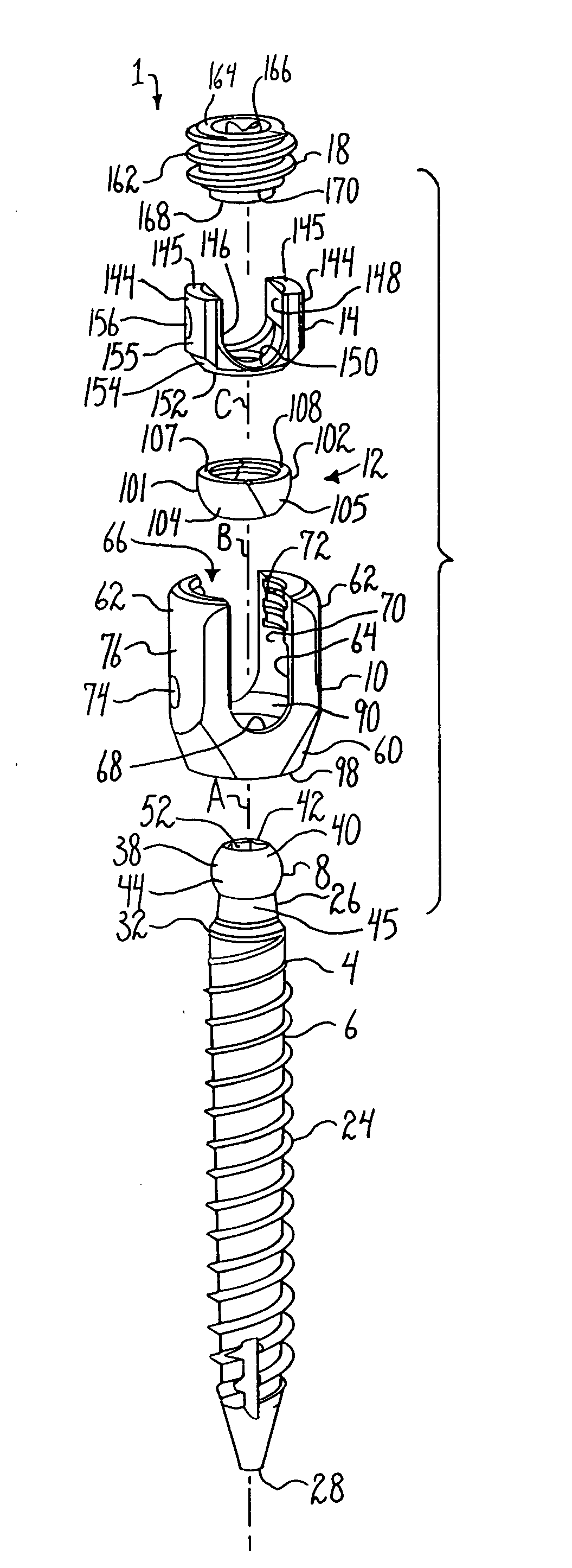
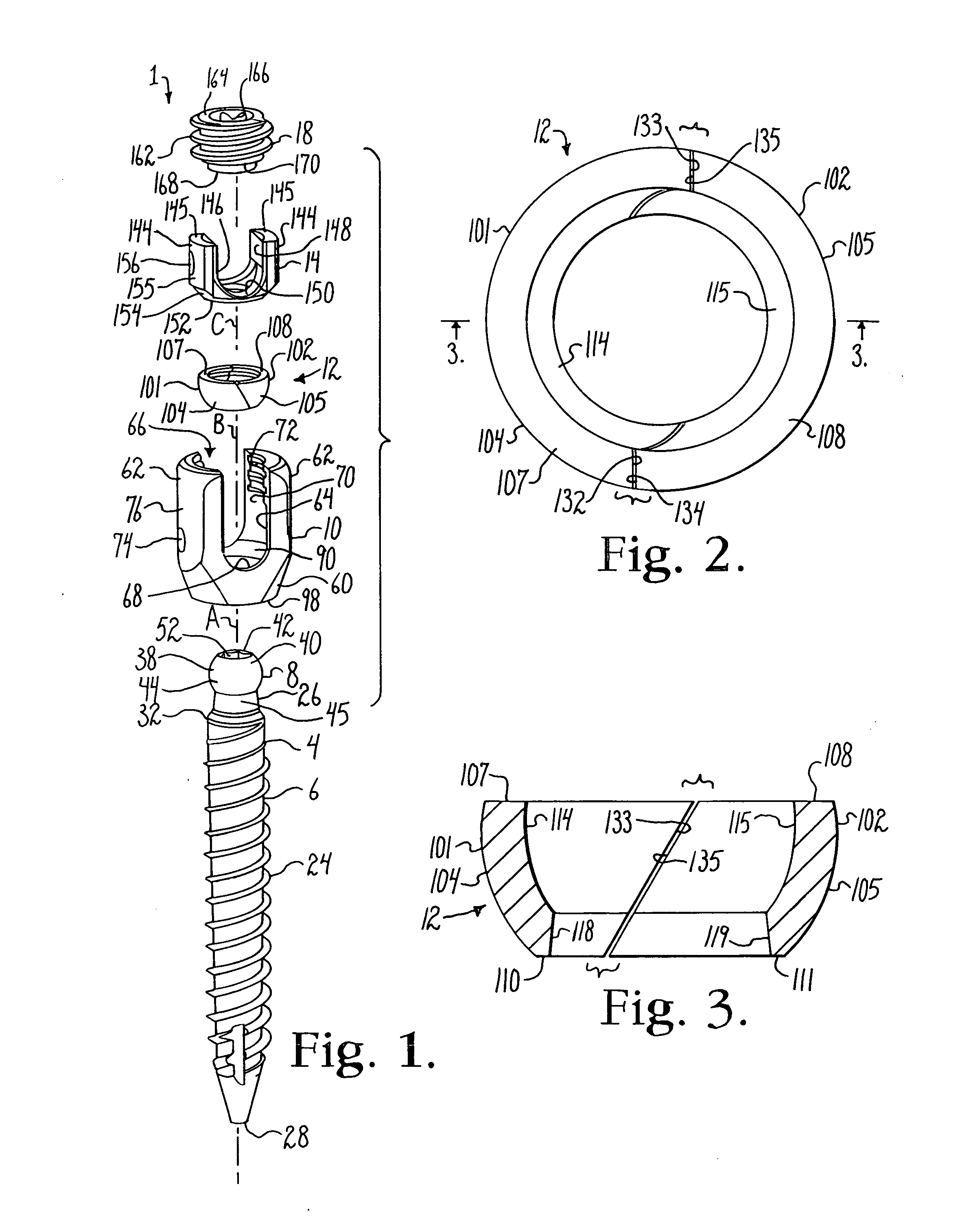
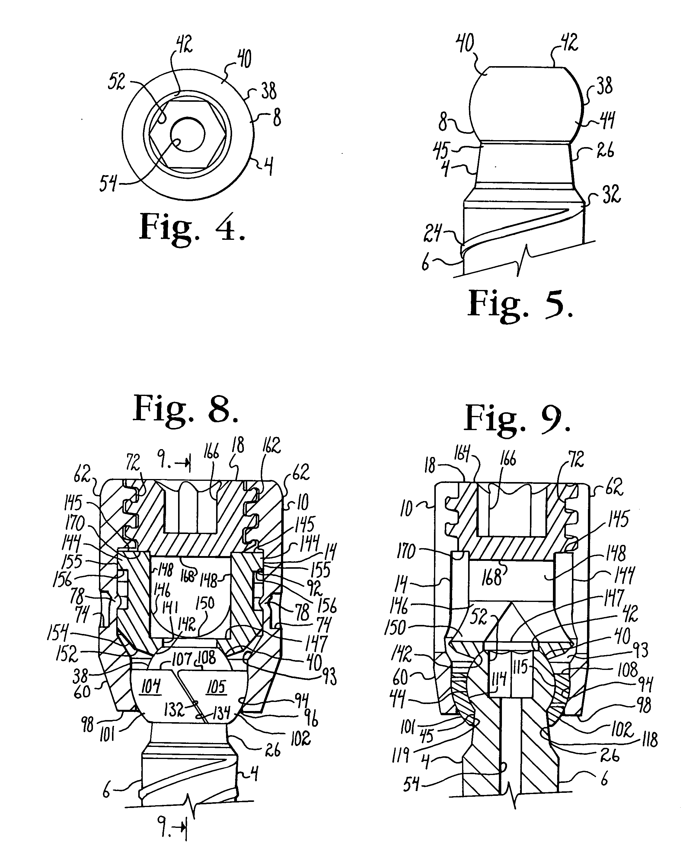
[0115]With reference to FIGS. 15-25, a polyaxial bone screw according to the invention, generally 201, includes a shank 204 having a body 206 and an upper portion 208, a receiver 210, a two-piece retainer 212, a compression insert 214, a pivot insert 216 and a closure structure 218 and is shown with a longitudinal connecting member in the form of a hard, inelastic, substantially non-deformable rod 221 having a substantially cylindrical outer surface 222. It is noted that the illustrated inserts and cooperating features of bone screws according to the invention may also be used with one-piece retainers or rings.

[0116]The shank 204 is identical or substantially similar in form and function to the shank 4 previously described herein with respect to the assembly 1. Thus, the shank 204 includes a thread 224, a neck 226, a tip 228, a spherical body 238 with an upper surface portion 240, a planar annular top 242, a lower surface portion / seating surface 244, a shank neck portion 245, and an...

third embodiment

[0128]With reference to FIGS. 28-47, a polyaxial bone screw according to the invention, generally 401, includes a shank 404 having a body 406 and an upper portion 408, a receiver 410, a two-piece retainer 412, a compression insert 414, a pivot insert 416 and a closure structure or top 418 and is shown with a longitudinal connecting member in the form of a rod 421 having a substantially cylindrical outer surface 422. The shank 404, retainer 412, compression insert 414, pivot insert 416, closure top 418 and rod 421 are substantially similar in form, function and materials to the respective shank 204, retainer 212, compression insert 214, pivot insert 216, closure top 218 and rod 221 previously described herein with respect to the assembly 201. However, some of the above-listed components of the assembly 401 include a few additional and / or alternative features. Therefore, each of the assembly components shall be briefly described below.

[0129]With particular reference to FIGS. 28 and 43...


PUM


Abstract

Polyaxial bone anchors include a retainer for holding a shank within a receiver, the retainer being in at least two discrete pieces and cooperating with a variety of inserts, some of which independently lock the polyaxial mechanism. Polyaxial and mono-axial bone anchor assemblies include pivot and / or pressure inserts or pads that cooperate with longitudinal connecting members to provide a desired degree of continued control of angulation of the longitudinal connecting member in the sagittal plane or to hold the connecting member in place. Pressure pads for deformable rods may also be made from a deformable plastic material.

Description

CROSS-REFERENCE TO RELATED APPLICATIONS[0001]This application claims the benefit of U.S. Provisional Patent Application Ser. No. 61 / 273,399, filed Aug. 4, 2009, the disclosure of which is incorporated by reference herein. This application is also a continuation-in-part of U.S. patent application Ser. No. 12 / 080,202 filed Apr. 1, 2008 that is a continuation-in-part of U.S. patent application Ser. No. 11 / 281,818 filed Nov. 17, 2005, now U.S. Pat. No. 7,625,396, that claims the benefit of U.S. Provisional Patent Application Ser. No. 60 / 630,478 filed Nov. 23, 2004, all of the disclosures of which are incorporated by reference herein. This application is also a continuation-in-part of U.S. patent application Ser. No. 12 / 229,207 filed Aug. 20, 2008 that claims the benefit of U.S. Provisional Patent Application Ser. No. 60 / 994,083 filed Sep. 17, 2007 and is a continuation-in-part of U.S. patent application Ser. No. 11 / 522,503 filed Sep. 14, 2006 that is a continuation-in-part of U.S. paten...

Claims


Application Information

Patent Timeline
Patent Type & Authority Applications(United States)
IPC IPC(8): A61B17/86
CPCA61B17/7008A61B17/7037A61B17/7032A61B17/7031
Inventor JACKSON, ROGER P.
Owner JACKSON
Why Eureka
Try Eureka