Porous medium exploitation method using fluid flow modelling

a fluid flow and exploitation method technology, applied in the field of underground media exploitation, can solve the problems of numerical calculation problems, calculating time, cpu time, stability or calculating time, etc., and achieve the effect of improving injectivity and productivity

Inactive Publication Date: 2010-11-25
INST FR DU PETROLE
View PDF7 Cites 50 Cited by
  • Summary
  • Abstract
  • Description
  • Claims
  • Application Information

AI Technical Summary

Benefits of technology

[0017]The invention provides improvement of the injectivity and the productivity of wells drilled through a porous medium, such as a hydrocarbon reservoir or a geologic CO2 storage reservoir.

Problems solved by technology

However, simultaneous flow simulations in the reservoir, which require a very large number of cells, and in the areas close to the well with smaller cells, which require small time steps to provide calculation stability, pose numerical calculation problems, in particular the problem of calculating time (CPU time).
Some delicate points such as convergence, stability or calculating time however pose problems in industrial applications.
Furthermore, the domain decomposition method is not always “conservative” (deterioration of the mass balance in the model as a function of time), which is not suitable for practical use of the method.
Besides, all these techniques require reformulation of the mathematical equations and of the boundary conditions developed in the flow simulators, and new developments are necessary to integrate the near and far well solutions in a single model, which is a long and difficult task.

Method used


Image

  • Porous medium exploitation method using fluid flow modelling
  • Porous medium exploitation method using fluid flow modelling
  • Porous medium exploitation method using fluid flow modelling

Examples


application examples

[0137]The coupling method according to the invention can be used for modelling various detailed phenomena around the well such as, for example, damage due to drilling or completion fluid, acid stimulation, non-Darcyan flow around the well, condensate gas problems, asphaltene deposition, damage due to CO2 injection, water or gas inflow prevention, sand encroachment, mineral deposits, completion impact, etc. Here, in particular is presented an application example for damage to the petroleum formation by the drilling fluid during well drilling, and an application example for water inflow prevention when a well under production produces a large amount of water in which this water production is to be reduced.

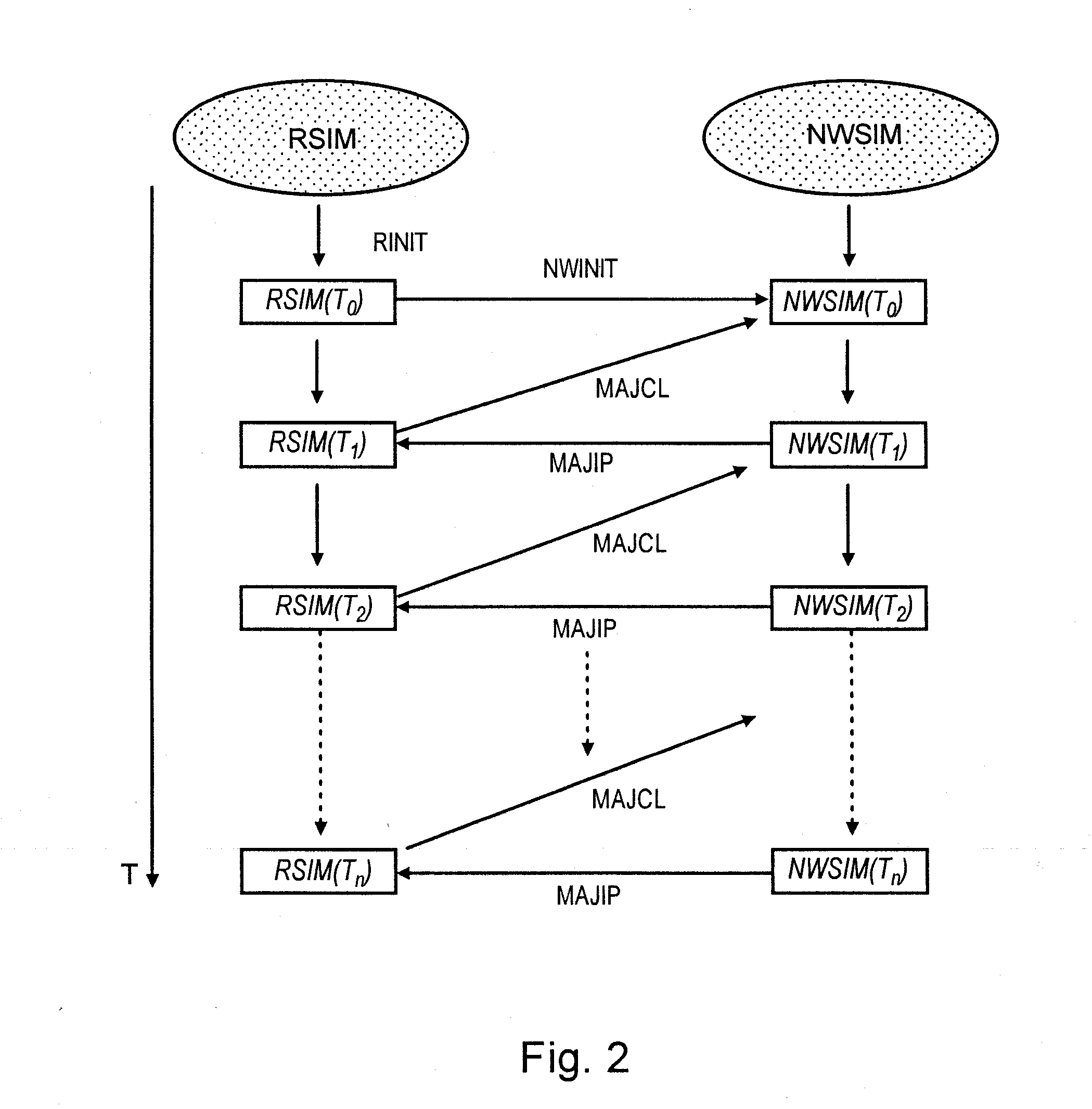
[0138]In order to further simplify the coupling method, the data are updated using the values at the time Tn, instead of the linear interpolation at a time between Tn, and Tn+1, for simulation of the near-wellbore model in the period from Tn, to Tn+1. This choice is interesting becau...


PUM


Abstract

Porous A porous medium exploitation method having application to petroleum exploitation is disclosed using coupling between a reservoir model and a near-wellbore model for modelling fluid flows. Fluid flows within the medium are simulated using a reservoir simulator and a near-wellbore simulator. At each time step, the boundary conditions used by the second simulator are calculated by means of with the reservoir simulator. Numerical productivity indices used by the reservoir simulator are calculated by means of using the near-wellbore simulator. The fluid flows within the porous medium during a given period of time are modelled by repeating the previous stages for several time steps. An optimum medium exploitation scenario is deduced determined from this modelling by taking into accounting for, for example, a well damage due to a drilling fluid, an injection of a polymer solution or of an acid solution in the well.

Description

BACKGROUND OF THE INVENTIONField of the Invention[0001]The present invention relates to underground media exploitation.DESCRIPTION OF THE PRIOR ART[0002]Local phenomena that may occur near a well, such as damage, have a tremendous impact on the injectivity or the productivity of a well. In the petroleum industry, it is very important to predict injectivity or productivity, especially when there are formation alterations in the vicinity of wells, which change the injection or production capacity of the well.[0003]Great efforts have been made for a long time by use of experimental techniques, in the laboratory, or numerical modelling methods, in order to take into account these local phenomena near wells, as well as their impact on injectivity or productivity.[0004]Numerical methods for modelling fluid flows within a well (injectivity and productivity of a well) comprise constructing two distinct models: the reservoir model and the near-wellbore model.[0005]A reservoir model comprises...

Claims


Application Information

Patent Timeline
Patent Type & Authority Applications(United States)
IPC IPC(8): G06G7/57
CPCE21B43/12
Inventor DING, DIDIER YURENARD, GERARD
Owner INST FR DU PETROLE
Why Eureka
Try Eureka