Front attachment for harvesting stalked plants

a technology for stalking plants and front attachments, which is applied in the field of front attachments for stalking plants to be harvested, can solve the problems of plant stalks falling out of the conveyor pockets, complicated and expensive control design, and material-conveyance problems

Active Publication Date: 2010-12-02
CLAAS SELBSTFAHRENDE ERNTEMASCHINEN GMBH
View PDF21 Cites 16 Cited by
  • Summary
  • Abstract
  • Description
  • Claims
  • Application Information

AI Technical Summary

Benefits of technology

[0006]The object of the present invention, therefore, is to avoid the disadvantages of the related art described above and, in particular, to provide a front attachment for harvesting stalked plants that ensures that the plants are conveyed reliably out of the front harvesting region, and that the plant stalks are transferred reliably to the downstream picking assemblies.

Problems solved by technology

A control that is designed for this purpose is complicated and expensive.
Cutting and conveyor disks having this type of design also have the disadvantage that they must convey large quantities of crop material, which, in the case of high rates of crop-material throughput, results in material-conveyance problems since the conveying capacity is often lower than would be required for high rates of crop-material throughput.
Stalk-cutting mechanisms designed in this manner have the disadvantage, however, that the plant stalks are likely to fall out of the conveyor pockets, due to the centrifugal force acting on them, as they travel from the front harvesting region to the rear transfer region.
When crop-material throughput rates are low in particular, this may cause the plant stalks to fall out of the conveyor elements before they are seized by the picking assemblies, which ultimately results in considerable material-flow problems.

Method used


Image

  • Front attachment for harvesting stalked plants
  • Front attachment for harvesting stalked plants
  • Front attachment for harvesting stalked plants

Examples


Embodiment Construction

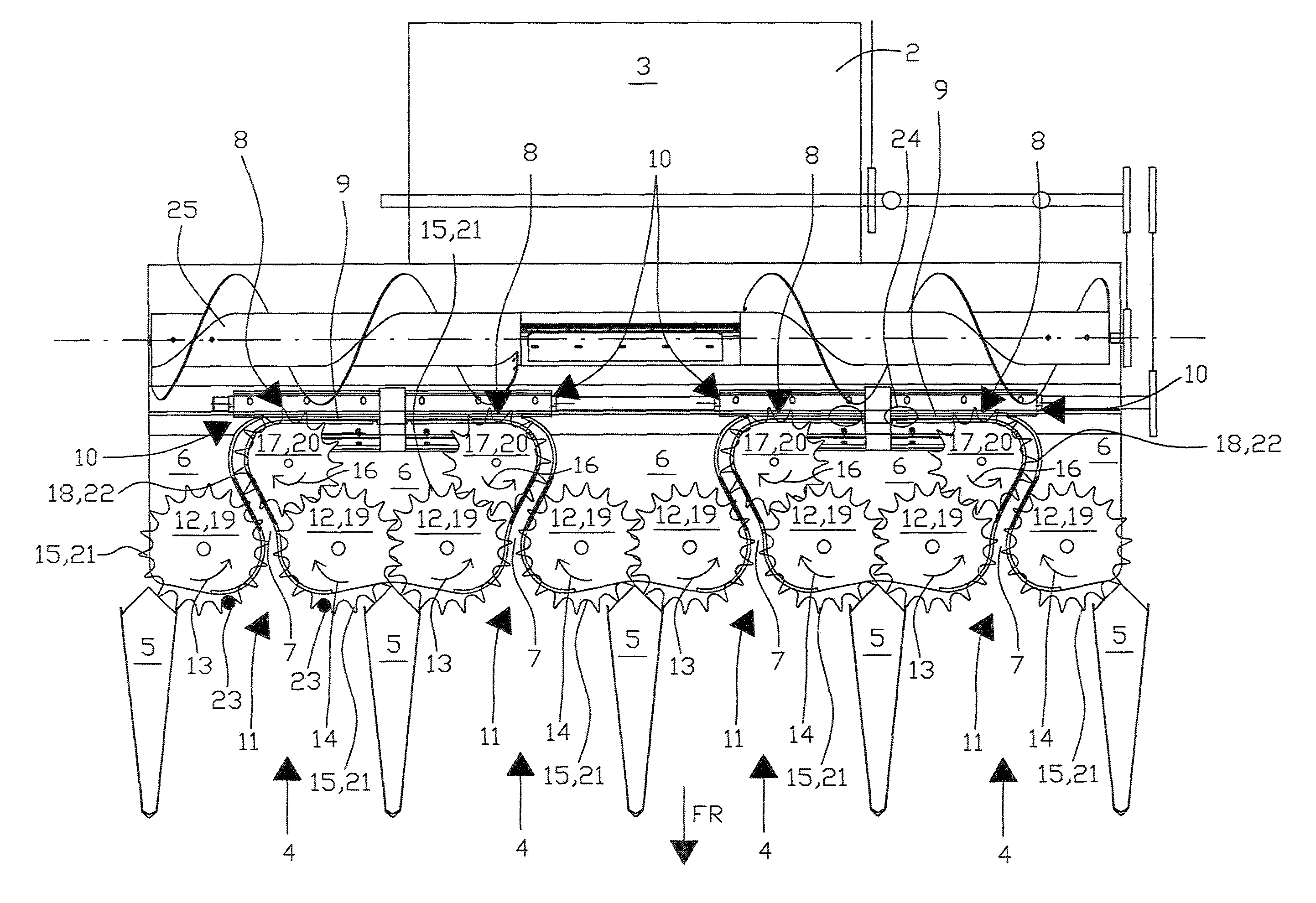
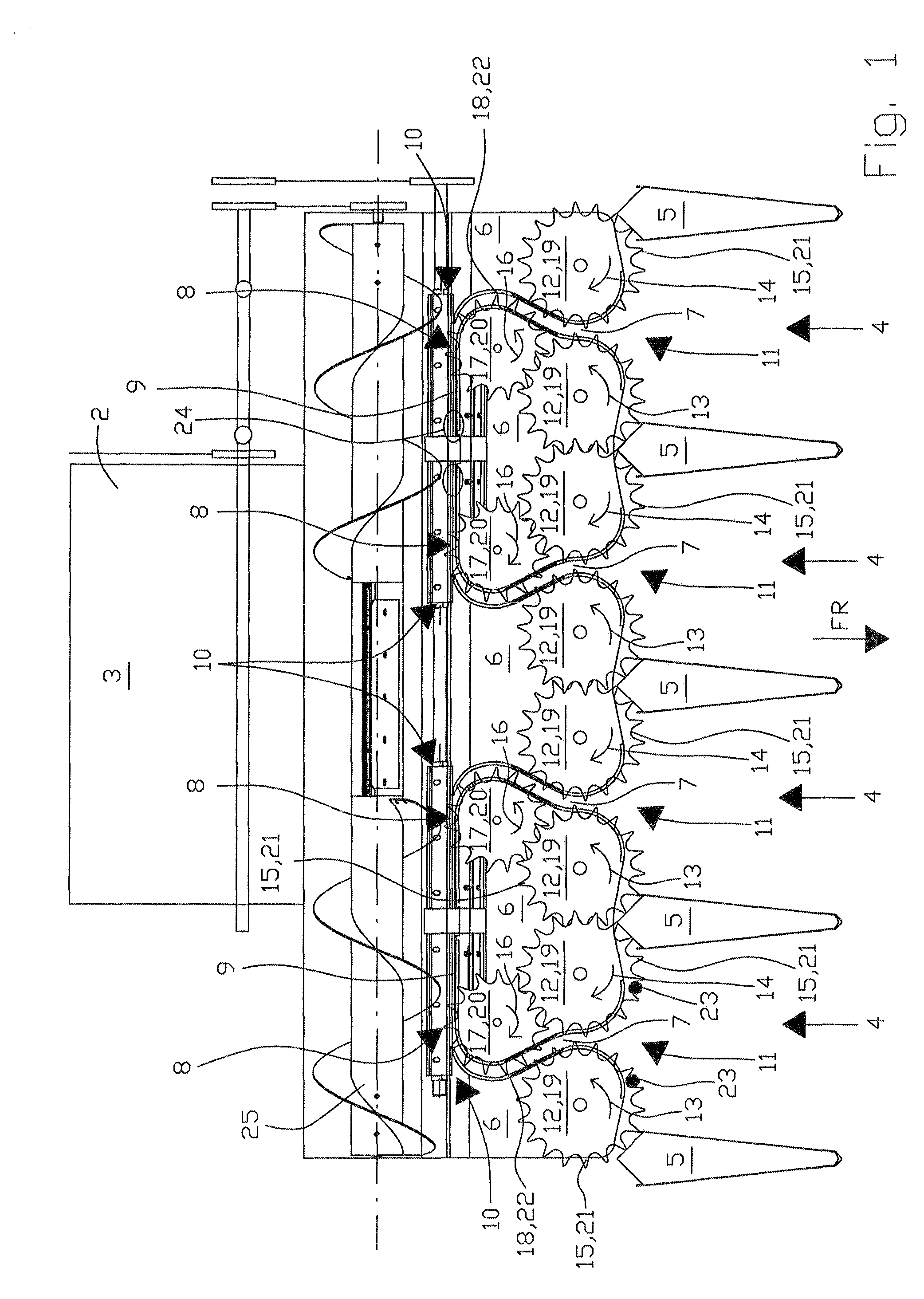
[0030]FIG. 1 shows a schematic depiction of front attachment 1, according to the present invention, for harvesting stalked plants, preferably corn, which is adapted in its rear region to feed rake 2 of a combine harvester 3 which is not depicted. In its front—relative to direction of travel FR—region, front attachment 1 includes a large number of intake conveyor mechanisms 4, each of which is separated from the other via forward-pointing dividers 5. Every intake conveyor mechanism 4 includes a guide channel 7 that is bordered by cover plates 6, and that leads, in a rear transition region 8, into picking channel 9 which extends transversely to direction of travel FR; a picking assembly 10 is assigned to each guide channel 7, on the underside, in a manner to be described in greater detail below.

[0031]In crop-material entry region 11, intake conveyor elements 12, which are situated in pairs and are driven in opposite directions of rotation as indicated by arrow directions 13, 14, are a...


PUM


Abstract

A front attachment for harvesting stalked plants has an intake conveyor mechanism that operates independently of the distance between rows, and a picking assembly located downstream thereof and transversely to the direction of travel, which separates the crops from the stalked plants and conveys them to a separate utilization, the plant stalks are guided in a guide channel from the intake conveyor mechanism to the picking channel, the guide channel is at least partially swept over, in the region of the intake conveyor mechanism, by driving elements of intake conveyor elements, which are situated in pairs and rotate in opposite directions, and, in the region of transfer to the picking assembly, the guide channel is at least partially swept over by driving elements of at least one rotating transfer element.

Description

CROSS-REFERENCE TO RELATED APPLICATION[0001]The invention described and claimed hereinbelow is also described in German Patent Application DE 10 2009 022 970.1 filed on May 28, 2009. This German Patent Application, whose subject matter is incorporated here by reference, provides the basis for a claim of priority of invention under 35 U.S.C. 119(a)-(d).BACKGROUND OF THE INVENTION[0002]The present invention relates to a front attachment for harvesting stalked plants.[0003]DE 197 34 747 made known a corn-harvesting front attachment of the type in question for installation on a self-propelled harvesting machine and that includes stalk-cutting mechanisms—which operate independently of the distance between rows—upstream of picking assemblies that separate the corn cobs from the plants and convey them to a separate utilization. In one variant of the embodiment, the picking assemblies, each of which is composed of picking rollers that operate in pairs, are located downstream of the particul...

Claims


Application Information

Patent Timeline
Patent Type & Authority Applications(United States)
IPC IPC(8): A01D45/02
CPCA01D45/025A01D45/021
Inventor LUETKE-HARMANN, TIMFOEGELING, WALTERAERDKER, BERNHARD
Owner CLAAS SELBSTFAHRENDE ERNTEMASCHINEN GMBH
Why Eureka
Try Eureka