Air volume flow and pushing force control device

a technology of air volume flow and control device, which is applied in the direction of vacuum cleaner equipment, sustainable buildings, sports equipment, etc., can solve the problem of not being able to control loops simultaneously, and achieve the effect of cost saving and higher costs

Inactive Publication Date: 2010-12-02
KURZ GERHARD
View PDF3 Cites 3 Cited by
  • Summary
  • Abstract
  • Description
  • Claims
  • Application Information

AI Technical Summary

Benefits of technology

[0027]In practice, this measure also leads to cost savings, since the determination of the pushing f

Problems solved by technology

However, the two control loops

Method used


Image

  • Air volume flow and pushing force control device
  • Air volume flow and pushing force control device

Examples


Embodiment Construction

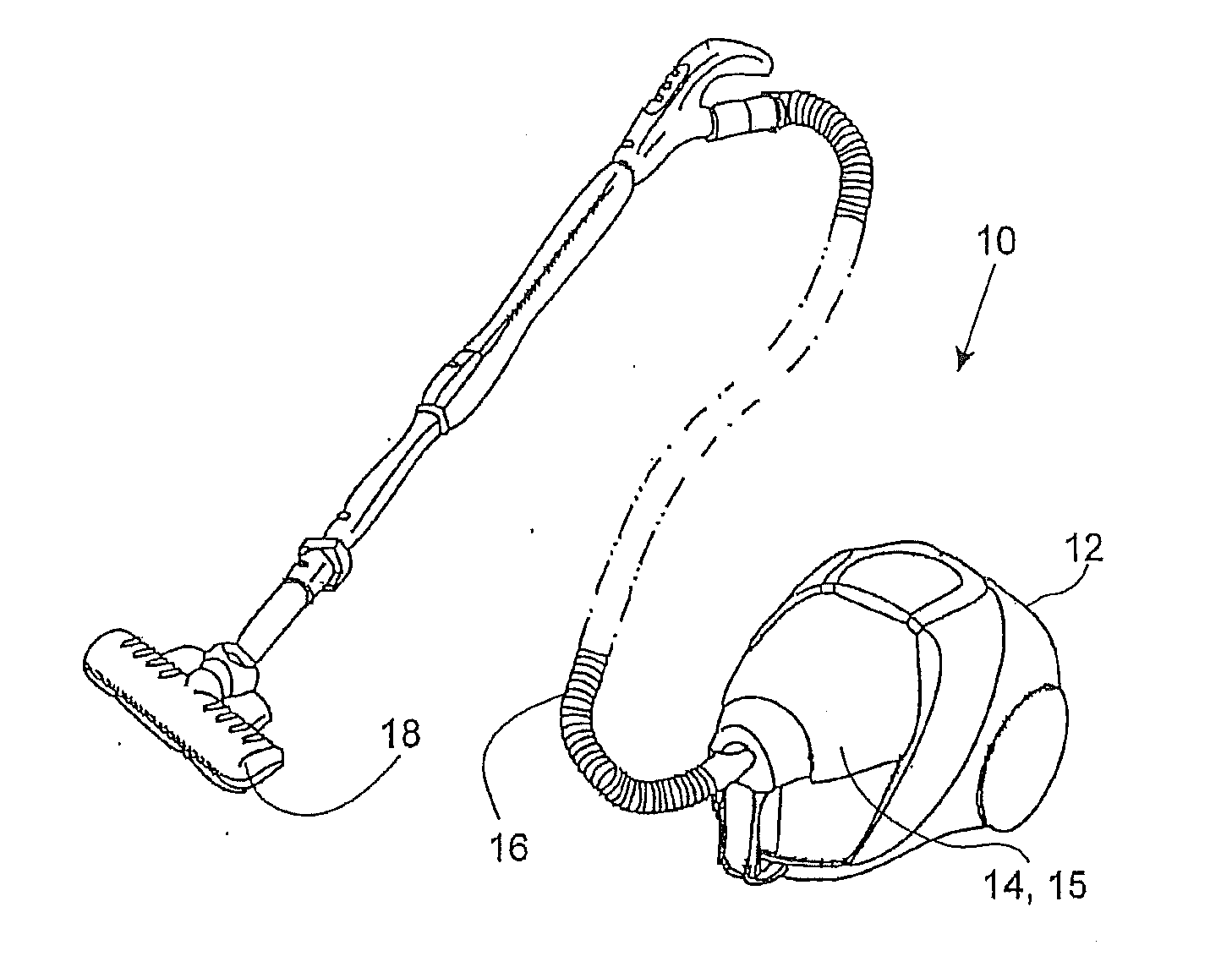
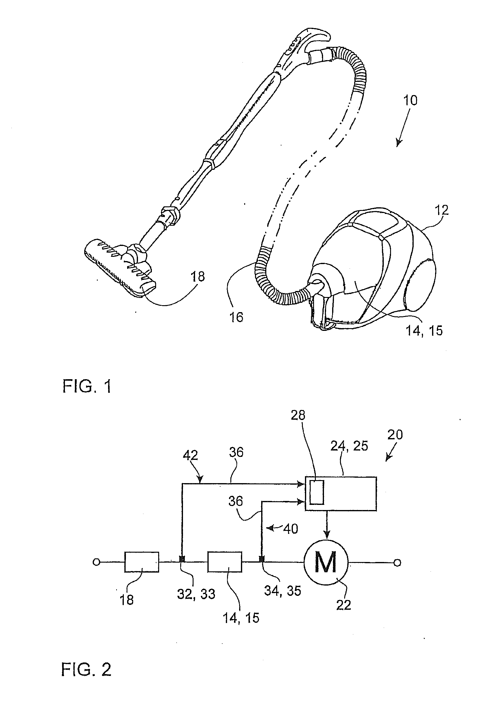
[0034]A vacuum cleaner, in particular a floor vacuum cleaner, is illustrated schematically in FIG. 1 and marked with the reference numeral 10. The floor vacuum cleaner 10 has a housing 12 that, in addition to a motor (not to be seen) also accommodates a dust bag receptacle 14 with a dust bag 15. Also included in the housing 12 is the electronics required to control the motor.

[0035]A hose and / or tube 16 passes from the vacuum cleaner housing 12 to a floor suction nozzle 18 that is pushed over a floor in order to clean the latter. Since the general design of such a floor vacuum cleaner is generally known, it will not be considered in further detail.

[0036]The air sucked in by the motor passes during suction via the floor suction nozzle 18 and the hose 16 into the dust bag 15, which filters out the dust particles, then passes the motor and once again reaches the outside from the vacuum cleaner housing 12. In order to keep the suction result constant, it is necessary to equalize the flow...


PUM


Abstract

The invention relates to an air volume flow and pushing force control device for a vacuum cleaner that has at least a motor, a dust receptacle and a suction nozzle, comprising a controller for controlling the motor power, a first sensor for detecting the air volume flow, which in conjunction with the controller forms a first control loop in order to maintain the air volume flow at a prescribed air volume flow value on the basis of the signal of the first sensor. The control device further comprises a second sensor for detecting a pushing force that is required for pushing the suction nozzle, and in conjunction with the controller, forms a second control loop in order to maintain the pushing force below a prescribed value on the basis of the signal of the second sensor, and a control loop selection device that activates one of the two control loops as a function of the signals of the two sensors.

Description

CROSS-REFERENCES TO RELATED APPLICATIONS[0001]This application is a continuation of copending international patent application PCT / EP2008 / 010115 filed on Nov. 28, 2008 and designating the U.S., which claims priority of German patent application DE 10 2007 057 589.2 filed on Nov. 28, 2007. The entire contents of these applications are incorporated herein by reference.BACKGROUND OF THE INVENTION[0002]The present invention relates to an air volume flow and pushing force control device for a vacuum cleaner that has at least a motor, a dust receptacle and a suction nozzle, comprising a controller for controlling the motor power, and a first sensor, for detecting the air volume flow, which in conjunction with the controller forms a first control loop in order to maintain the air volume flow at a prescribed air volume flow value on the basis of the signal of the first sensor.[0003]Air volume flow control devices for vacuum cleaners are generally known. They are used for the purpose of main...

Claims


Application Information

Patent Timeline
IPC IPC(8): A47L9/00
CPCA47L9/02A47L9/2805Y02B40/82A47L9/2842A47L9/2857A47L9/2821Y02B40/00
Inventor SCHULZ, DETLEFSTREHLER, THOMASHERMANN, RUDOLFILLIG, ROLANDLEHMANN, PETERHAMM, SILVIO
Owner KURZ GERHARD
Why Eureka
Try Eureka