Shock absorbing apparatus

a technology of shock absorption and shock absorber, which is applied in the direction of shock absorbers, elastic dampers, bumpers, etc., to achieve the effect of efficiently absorbing shock energy and controlling an amount of absorbed energy

Inactive Publication Date: 2010-12-02
TOYODA GOSEI CO LTD
View PDF18 Cites 10 Cited by
  • Summary
  • Abstract
  • Description
  • Claims
  • Application Information

AI Technical Summary

Benefits of technology

[0038]In accordance with the first shock absorbing apparatus according to the present invention, a colliding object and the pressure-receiving plate portion first make a point contact, and then shock energy is absorbed by the ribs that deform, and by the inclusion that is compressed. In a case where the shock energy is greater than those being absorbed by such an extent, one of the ribs, which is the closest to the contact point, first buckles, and thereafter the contact area augments gradually because the colliding object presses the pressure-receiving plate portion, and so a plurality of the ribs buckle. And, the shock energy is absorbed by the deformations of the ribs and the compression of the inclusion.
[0039]And, as a result of the action that the shock energy is absorbed, although energy that the colliding object possesses decreases gradually, the contact area between the colliding object and the shock absorbing apparatus augments, and thereby a force that is applied to per unit area of the shock absorbing apparatus decreases acceleratedly. However, in that process, the fragile section of the ribs fractures, and thereby the inclusion flows into the adjoining vacant minor compartments through the resulting fractured section. Therefore, not only the spring back resulting from the compression of the inclusion dissolves, but also the shock energy is absorbed by means of circulation resistance to the inclusion.
[0040]By making energy, which is absorbed by means of circulation resistance to the inclusion, smaller than energy, which is absorbed by means of the buckling of the ribs or the compression of the inclusion, it is possible to absorb the shock energy efficiently even when the shock energy, which is applied toper unit area of the shock absorbing apparatus, has decreased. As a result, it is possible to absorb the shock energy even at a later stage in absorbing the shock, and thereby it is possible to retard the occurrence of the “bottom sticking” phenomenon.
[0041]Although it is allowable that there can be such cases that the other filled minor compartments adjoin the filled minor compartments, it is difficult for the inclusion to flow into the adjoining filled minor compartments. Therefore, it is desirable that only a plurality of the vacant minor compartments can adjoin the filled minor compartments.
[0042]It is preferable that the filled minor compartments, and the vacant minor compartments can make a cylindrical shape whose cross section is a regular hexagon. By doing thusly, it is possible to dispose the filled minor compartments and vacant minor compartments densely as a honeycomb shape, and thereby the right-angle-wise strength with respect to impact directions upgrades. Moreover, it is possible to make the inclusion flow into one to six pieces of the vacant minor compartments that adjoin one of the filled minor compartments, and then it becomes feasible to control an amount of absorbed energy by controlling the number of the vacant minor compartments into which the inclusion flows.
[0043]When the fragile section is made into a through hole, there might arise such a case that it becomes difficult to absorb the energy of shock by means of compressing the inclusion at an initial stage in absorbing the shock. Therefore, it is desirable that the fragile section can be made into a thin-walled section, or a notch.

Problems solved by technology

Accordingly, at a later stage in absorbing the shock, it becomes difficult to buckle the ribs, and so there has been such a problem that the “bottom sticking” phenomenon occurs as a consequence so that the reactive force from the shock absorbing apparatus augments.
Moreover, there might also be such another problem that, at a later stage in absorbing the shock, the debris of the ribs intervene between the pressure-receiving plate portion, which has received the shock, and the facing plate portion, which faces the pressure-receiving plate portion, because the debris of the buckled ribs come to remain in the hollow section; accordingly, load rises sharply at the time when the pressure-receiving plate portion and facing plate portion come in contact with the debris of the ribs, and consequently results in the problem that the “bottom sticking” phenomenon occurs so that the reactive force from the shock absorbing apparatus augments.

Method used


Image

  • Shock absorbing apparatus
  • Shock absorbing apparatus
  • Shock absorbing apparatus

Examples


examples

[0098]Hereinafter, the present invention will be explained in detail by means of examples.

example no.1

Example No. 1

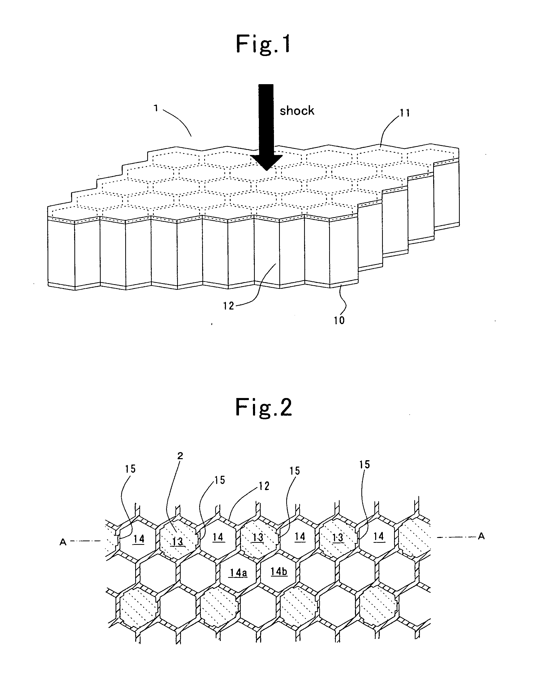
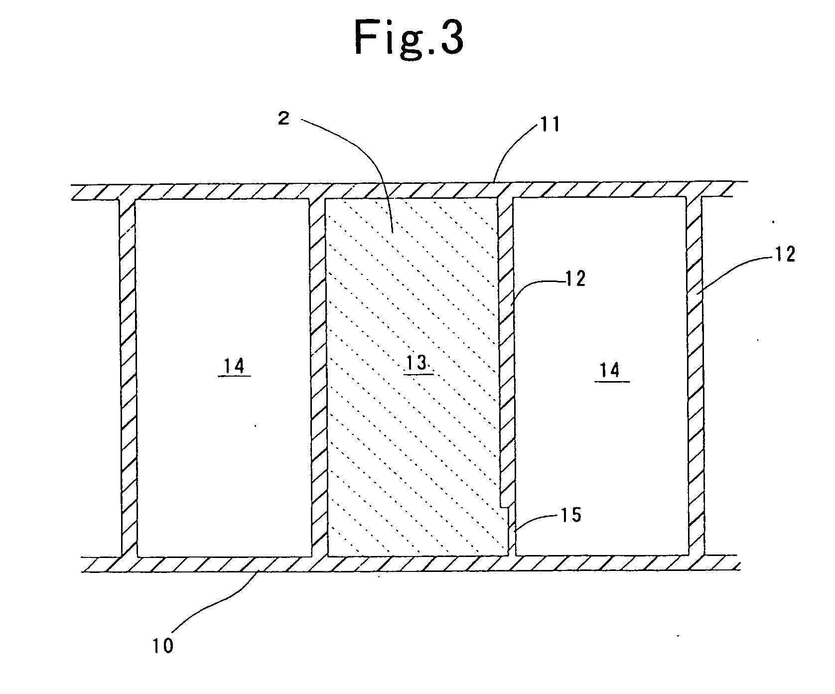
[0099]A shock absorbing apparatus according to the present example is illustrated in FIG. 1. This shock absorbing apparatus is constituted of a facing plate portion 10, a pressure-receiving plate portion 11 that is separated from the facing plate portion 10 by an interval and is put in place parallelly thereto, and checkered ribs 12 that not only connect between the facing plate portion 10 and the pressure-receiving plate portion 11 but also divide a space being formed between the facing plate portion 10 and the pressure-receiving plate portion 11 into a plurality of minor compartments. The minor compartments, which are formed by the checkered ribs 12 as well as the facing plate portion 10 and pressure-receiving plate section 11, make a regular hexagon in the cross section, respectively; and are formed as a honeycomb shape as a whole.

[0100]The multiple minor compartments, as FIG. 2 illustrates their cross sections, comprise: filled minor compartments 13 that are filled ...

example no.2

Example No. 2

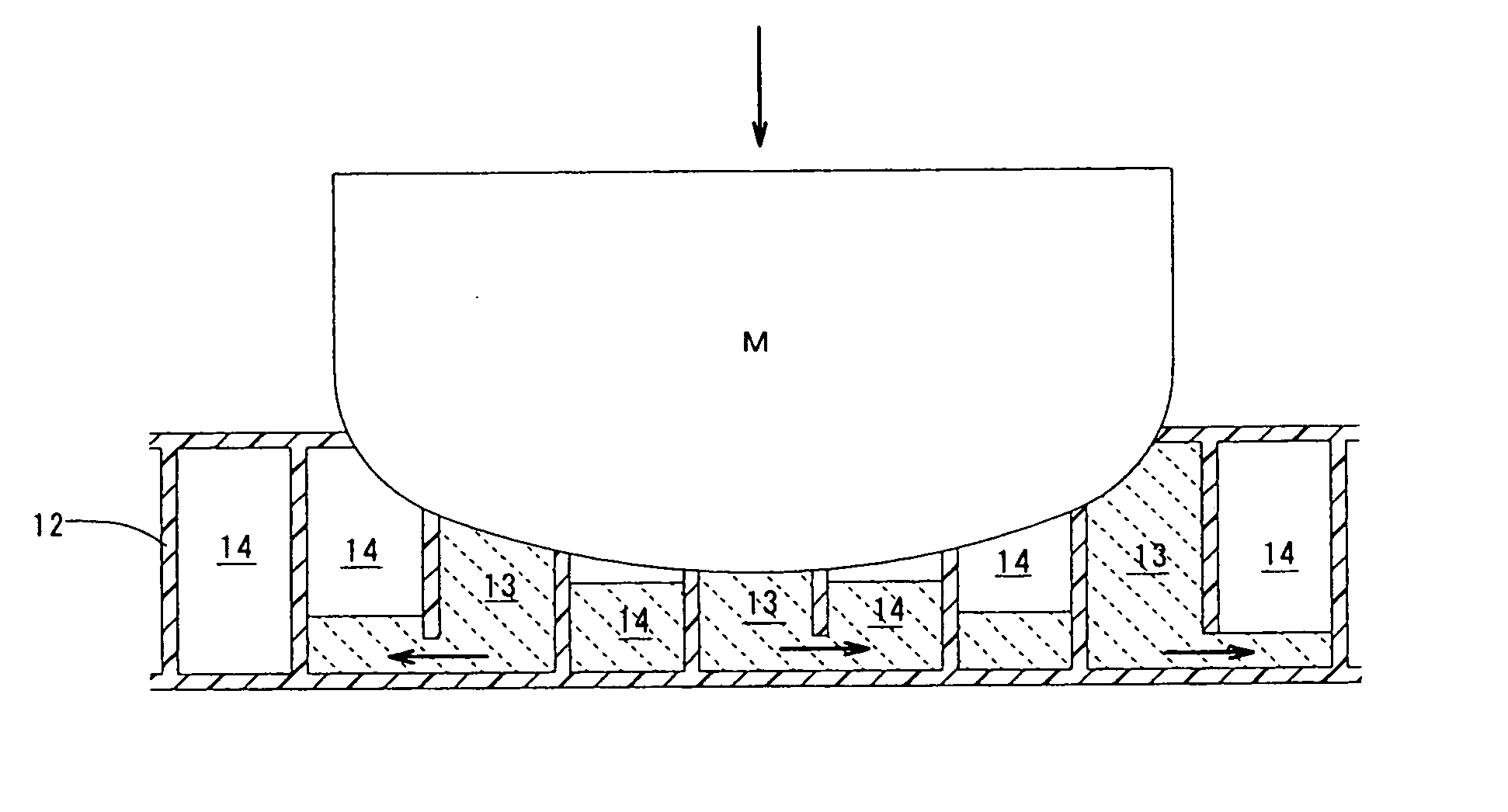
[0107]However, in the shock absorbing apparatus 1 according to Example No. 1, there might arise a case where it is difficult for the inclusion 2, which has flowed into the vacant minor compartments 14 through the fractured thin-walled sections 15, to flow out from the vacant minor compartments 14. For example, although the vacant minor compartment 14a specified in FIG. 2 allows the inclusion 2 to flow into it from one of the adjoining filled minor compartments 13, but it is not possible for the inclusion 2 to flow out from it to the other adjoining vacant minor compartment 14b, and the like. Therefore, in a case where the colliding object “M” intrudes into it furthermore so that it comes in contact with the inclusion 2 in the filled minor compartments 13 and vacant minor compartments 14 that are communicated with each other by way of the fractured thin-walled sections 15, the inclusion 2 comes to be compressed so that the spring back might be afraid of.

[0108]Hence, in a...


PUM


Abstract

While comprising filled minor compartments being filled with an inclusion in which a liquid makes the major component, and vacant minor compartments being filled with the air, at least one of the vacant minor compartments adjoins the filled minor compartments, and a fragile section is formed in at least one of ribs that demarcate the filled minor compartments and the adjoining vacant minor compartments. After the fragile section has fractured, shock energy can be absorbed furthermore by means of circulation resistance to the inclusion that flows from the filled minor compartments to the vacant minor compartments.

Description

TECHNICAL FIELD[0001]The present invention relates to a shock absorbing apparatus that is put in place inside door trims, front pillars, bumpers, and the like, and which absorbs shock energy at the time of collision, and so forth. A shock absorbing apparatus according to the present invention can be utilized not only for automotive applications but also for a variety of fields.BACKGROUND ART[0002]As conventional shock absorbing apparatuses, the following have been known heretofore: hydraulic buffering apparatuses in which pistons compress liquids, thereby relieving shocks; or those which absorb shock energies by pneumatic compression resistance while letting air escape through air pin holes; and the like.[0003]Moreover, in recent years, many shock absorbing apparatuses have been used extensively, shock absorbing apparatuses which are made by disposing a large number of resinous ribs inside door trims, and which absorb shock energies by means of the buckling of the resinous ribs and ...

Claims


Application Information

Patent Timeline
Patent Type & Authority Applications(United States)
IPC IPC(8): F16F7/00F16F7/12
CPCF16F7/121B60J5/0441B60J5/0461B60R2021/0435B60R21/04B60R21/0428B60R2021/0407B60R19/20
Inventor TOTANI, CHIHARUFURUTANI, MUNEOSUENAGA, KIYOSHISHIRAKI, TAKEHIKOYABUYA, SHIGERUKATAGIRI, KATSUHIROITO, KATSUSHI
Owner TOYODA GOSEI CO LTD
Why Eureka
Try Eureka