

Rotor and Motor
a rotor and motor technology, applied in the direction of dynamo-electric machines, magnetic circuit rotating parts, dynamo-electric machines, etc., can solve the problems of lowering the rotation performance and unbalance of magnetic forces, and achieve the effect of optimizing the shape of each salient pole and improving rotation performan
- Summary
- Abstract
- Description
- Claims
- Application Information
AI Technical Summary
Benefits of technology
Problems solved by technology
Method used
Image

Examples
first embodiment
[0049]A first embodiment of the present invention will now be discussed with reference to FIGS. 1 to 3.
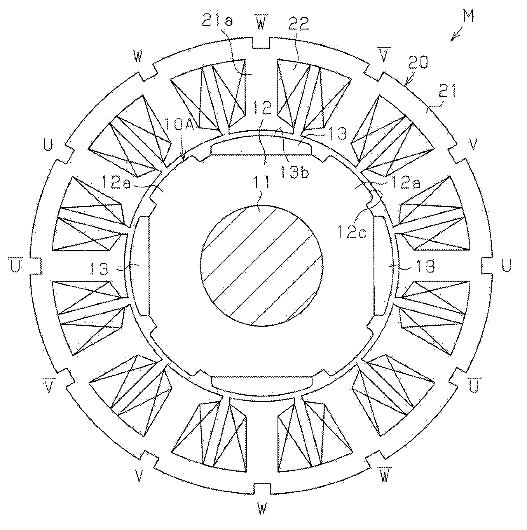
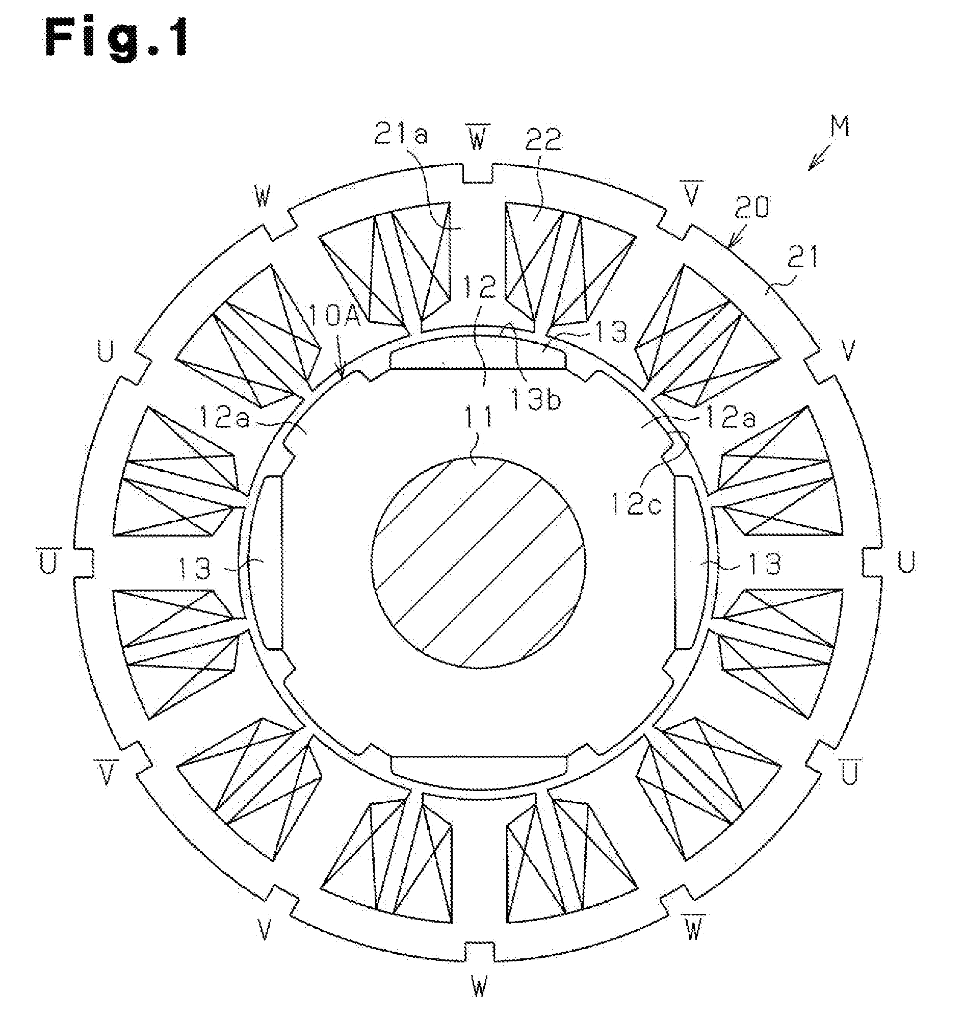
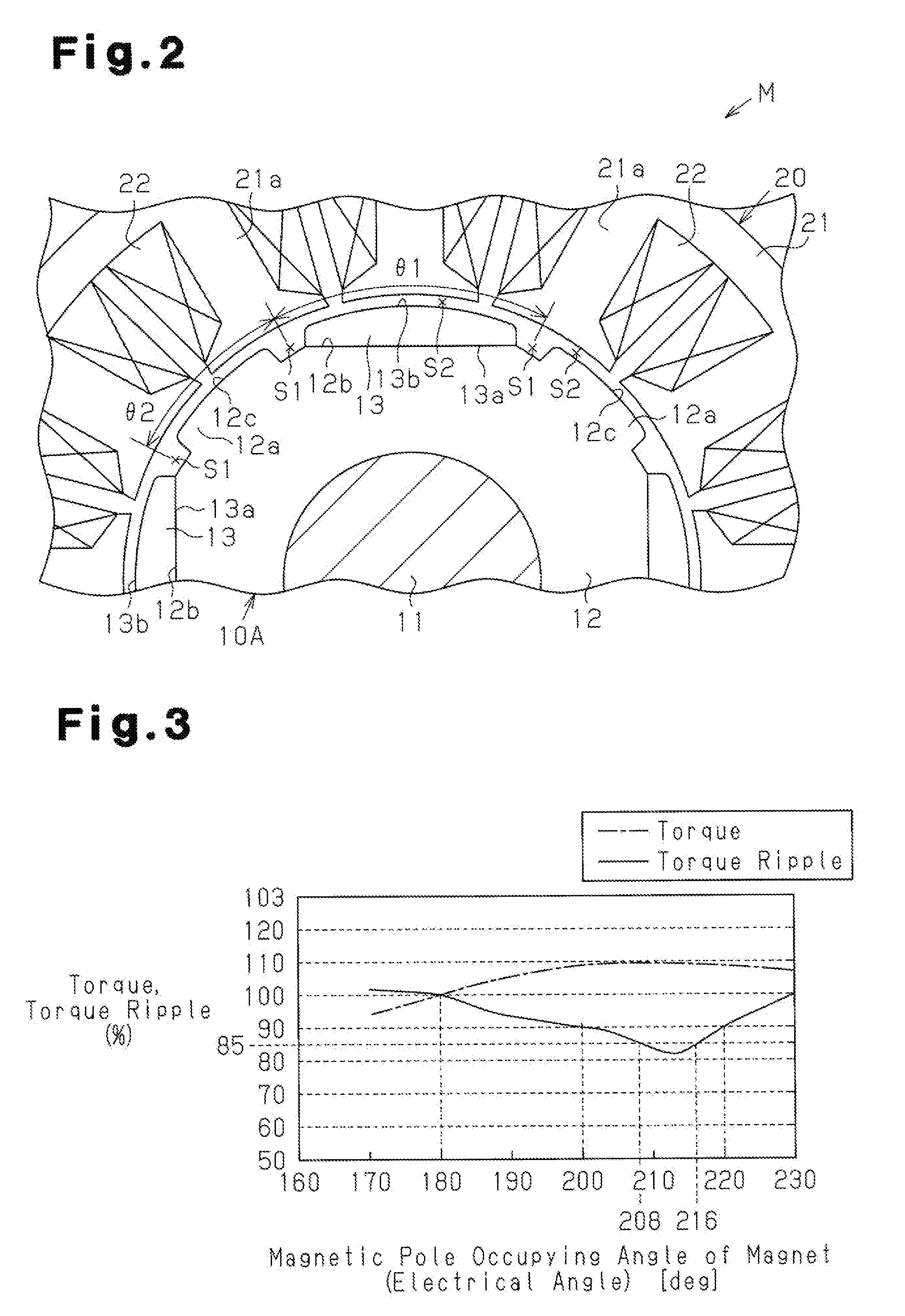
[0050]FIGS. 1 and 2 show an inner rotor type brushless motor M. The motor M of the first embodiment uses a rotor 10A including a substantially annular rotor core 12, which is formed from a magnetic metal material and fixed to an outer circumferential surface of a rotation shaft 11, four N-pole magnets 13, which are arranged along the circumferential direction of the rotor core 12, and salient poles 12a, which are formed integrally with the rotor core 12 and arranged between adjacent ones of the magnets 13 in the circumferential direction. The salient poles 12a function as S-poles. In other words, the rotor 10A is a so-called consequent pole type having eight magnetic pole portions. A stator 20 includes a stator core 21, which has twelve teeth 21a, and coils 22, which are wound around the teeth 21a. Slots for accommodating the coils 22 are formed between the teeth 21a that are adjac...
second embodiment
[0067]A second embodiment of the present invention will now be discussed with reference to FIGS. 4 to 8.
[0068]In the second embodiment, the quantity of magnetic pole portions in the rotor differs from the first embodiment. Accordingly, the same reference numerals are given to those components that are the same as the corresponding components of the first embodiment. Such components will not be described in detail.
[0069]As shown in FIGS. 4 and 5, the motor M of the second embodiment uses a rotor 10B includes five N-pole magnets 13, which are arranged along the circumferential direction of the rotor core 12, and five salient poles 12a, arranged between adjacent ones of the magnets 13 in the circumferential direction. The salient poles 12a function as the S-poles. In other words, the rotor 10B is a so-called consequent pole type having ten magnetic pole portions. The stator 20 includes twelve teeth 21a in the same manner as in the first embodiment. That is, the ratio X1:X2 of the magne...
third embodiment
[0092]A third embodiment of the present invention will now be discussed with reference to FIGS. 9 to 11.
[0093]In the third embodiment, the quantity of magnetic pole portions of the rotor differs from the first embodiment. Accordingly, the same reference numerals are given to those components that are the same as the corresponding components of the first embodiment. Such components will not be described in detail.
[0094]As shown in FIGS. 9 and 10, the motor M of the third embodiment uses a rotor 10C including seven N-pole magnets 13, which are arranged along the circumferential direction of the rotor core 12, and seven salient poles 12a, which are arranged between adjacent ones of the magnets 13 in the circumferential direction. The salient poles 12a function as the S-poles. In other words, the rotor 10C is a so-called consequent pole type having fourteen magnetic pole portions. The stator 20 includes twelve teeth 21a in the same manner as the first embodiment. That is, in the brushle...
PUM
 Abstract
Description
Claims
Application Information