Integrated water detector

a detector and water sensor technology, applied in the field of water sensors, can solve the problems of damage to the appliance itself, and the damage to the surrounding environment, and save homeowners millions of dollars in damages

Inactive Publication Date: 2010-12-02
ALTOR LTD LC
View PDF41 Cites 19 Cited by
  • Summary
  • Abstract
  • Description
  • Claims
  • Application Information

AI Technical Summary

Benefits of technology

[0012]Among other aspects and advantages, the new and improved leak detector pad of the present disclosure is compact, ruggedized, waterproof, includes no moving parts, is protected from dirt and corrosion, and can be reused after a flood. In addition, the DC voltage alarm signal produced by the leak detector pad can be transmitted a relatively long distance.

Problems solved by technology

Household flooding costs homeowners and insurance companies millions of dollars in damages every year in the United States alone.
Bursting pipes or leaking or malfunctioning appliances, for instance, can cause such household flooding.
The resultant flooding often causes damage to the surrounding environment as well as to the appliance itself.
However, unless the manually operated shut-off valves, which are typically positioned at the wall behind most washing machines, are closed, water can surge unrestricted through a burst supply hose or can spill from the tank of the malfunctioning washing machine.
Clearly, in an unmonitored situation, the flow of water will rapidly exceed the storage capacity of a catch basin and also can exceed the capacity of a drain positioned within the catch basin.
Toilets can be a source of flooding as well.
If a drain line of the toilet becomes plugged, or if the float valve or seal malfunctions, water can spill from within the toilet bowl or refill tank onto the floor.
In addition, the water supply line to the toilet can become loosened or can fail.
Thus, large amounts of water can flood a bathroom if the condition remains unmonitored.
Water heaters can also be a source of flooding.
Such mechanical devices may become inoperative as a result of any of a number of impediments such as biological growth, dust, grime, corrosion, ice, flotsam, and the like.
Such mechanical devices are typically also not capable of detecting water to shallow depths, e.g., less than one eighth of an inch.

Method used


Image

  • Integrated water detector
  • Integrated water detector
  • Integrated water detector

Examples


Embodiment Construction

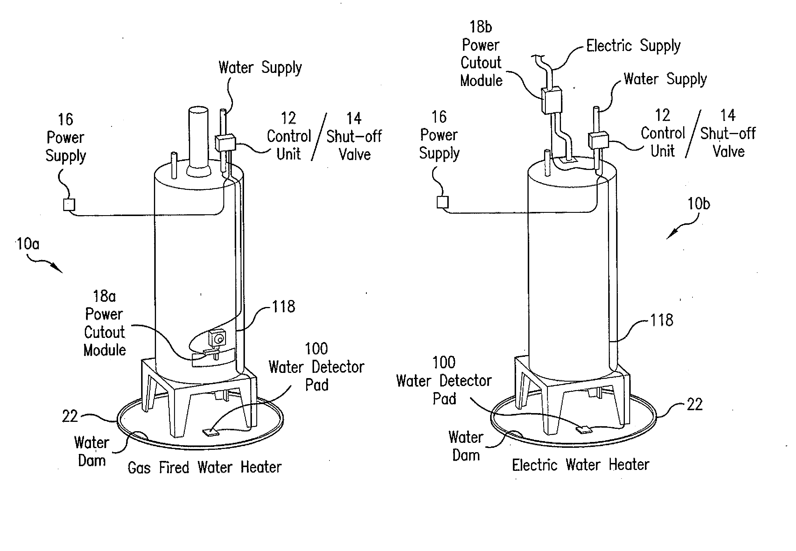
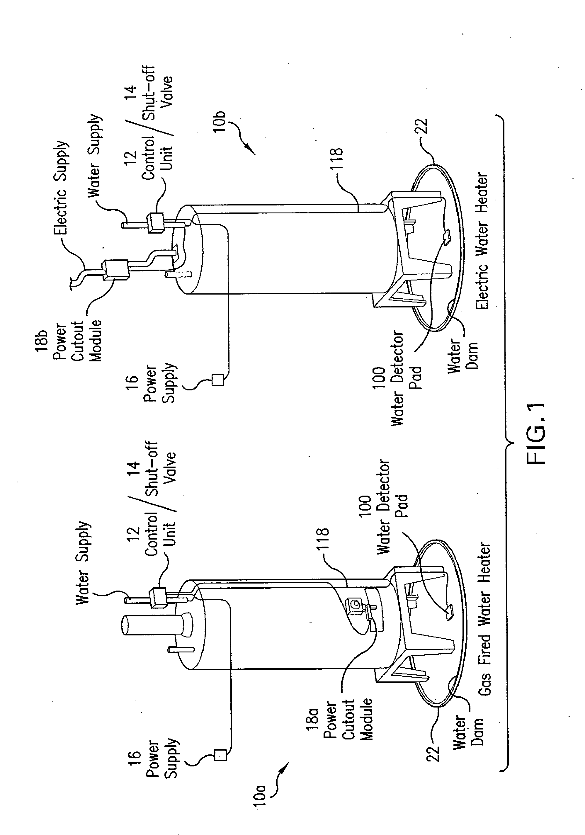
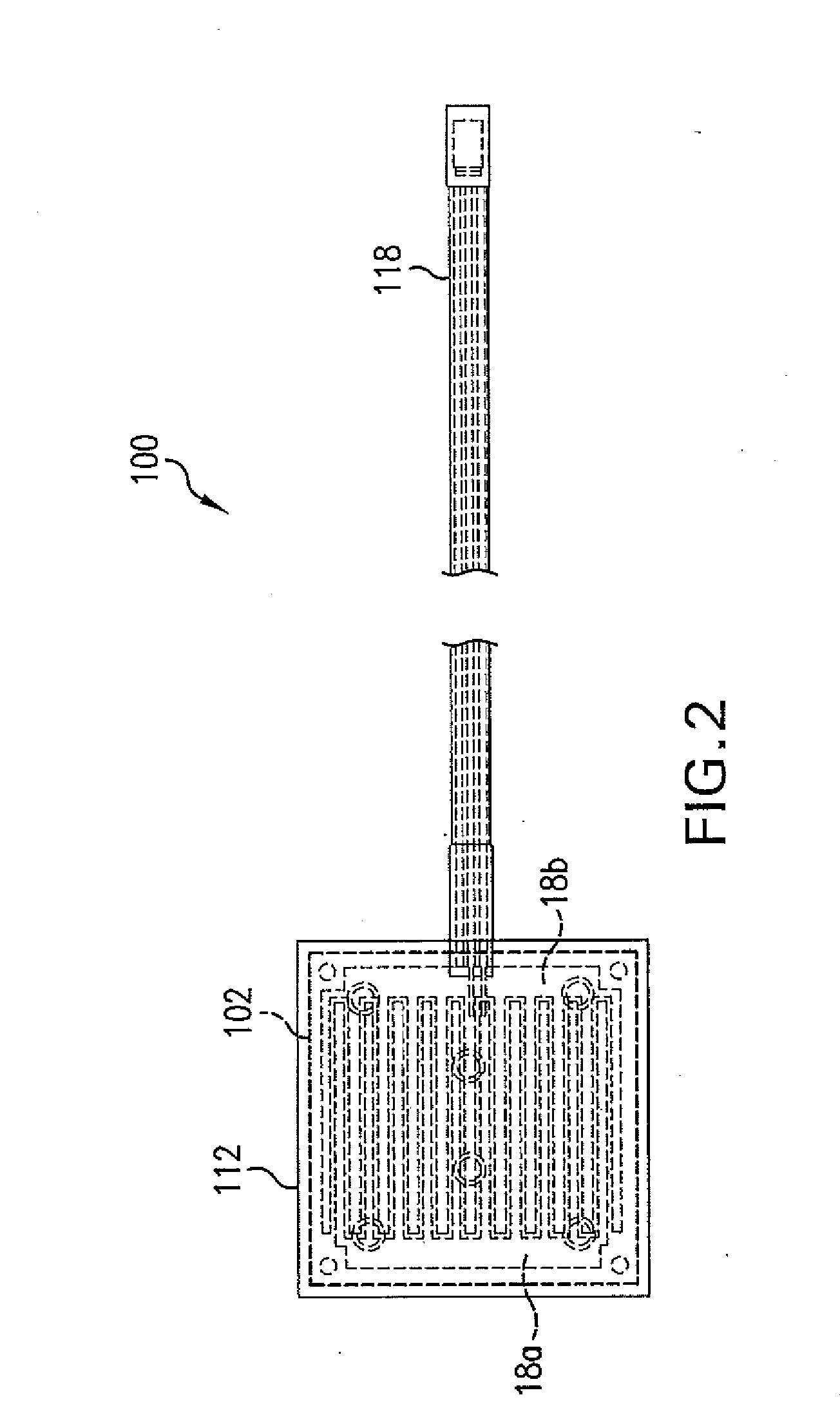
[0036]Referring to FIG. 1, there are shown two exemplary embodiments of water heater leak detector shut-off systems 10a, 10b including new and improved leak detector pads 100 constructed in accordance with the present disclosure. Among other benefits, the new and improved leak detector pad 100 of the present disclosure is compact, ruggedized, waterproof, includes no moving parts, is protected from dirt and corrosion, and can be reused after a flood. In addition, the leak detector pad 100 can transmit a signal a relatively long distance, such as 150 feet. FIGS. 2-13 provide further detailed views of the detector pad 100, but first the shut-off systems 10a, 10b are discussed to provide background information for the detector pad.

[0037]In FIG. 1 there is shown a gas water heater and an electric water heater. In both cases, the shut-off systems 10a, 10b include a control unit 12, a water supply shut-off valve 14, and a power supply 16 in addition to the leak detector pads 100. The power...


PUM


Abstract

A leak detector pad comprising a circuit board having a bottom surface and a top surface, spaced first and second electrically conductive traces located on the bottom surface, and an electronic circuit mounted on the top surface. The circuit includes a first segment adapted to create an alternating current (AC) voltage waveform, a second segment adapted to apply the AC voltage waveform between the traces on the bottom surface of the circuit board, a third segment adapted to create a measure of a capacitance between the traces based upon an AC current flowing between the traces as a result of the AC voltage waveform, and a fourth segment adapted to create a direct current (DC) voltage alarm signal if the measure of capacitance provided by the third segment indicates the presence of fluid.

Description

CROSS-REFERENCE TO RELATED APPLICATION[0001]This application claims priority to U.S. Provisional Patent Application No. 60 / 884,566 filed Jan. 11, 2007 and also claims priority as a continuation-in-part to U.S. patent application Ser. No. 12 / 008,525 filed on Jan. 11, 2008, now issued as U.S. patent No. on June, 2010, each of which is incorporated herein by reference.TECHNICAL FIELD OF THE DISCLOSURE[0002]The present disclosure generally relates to a water sensor and, more particularly, to a water detector integrated into another device. Even more particularly, the present disclosure relates to an integrated water detector for marine applications and other harsh conditions that can preferably work on low water levels such as an eighth of an inch or less.BACKGROUND OF THE DISCLOSURE[0003]Household flooding costs homeowners and insurance companies millions of dollars in damages every year in the United States alone. Bursting pipes or leaking or malfunctioning appliances, for instance, c...

Claims


Application Information

Patent Timeline
Patent Type & Authority Applications(United States)
IPC IPC(8): G08B21/00
CPCG01M3/16
Inventor WOOD, JONATHAN R.
Owner ALTOR LTD LC
Why Eureka
Try Eureka