Display device

a technology of display device and bezel, which is applied in the field of display device, can solve the problems affecting the enjoyment of viewing, and affecting the appearance of flat display device, etc., and achieves the effect of reducing the width of the bezel par

Active Publication Date: 2010-12-02
SAMSUNG DISPLAY CO LTD
View PDF10 Cites 33 Cited by
  • Summary
  • Abstract
  • Description
  • Claims
  • Application Information

AI Technical Summary

Benefits of technology

[0010]Accordingly, embodiments of the present invention have been made to solve the above-mentioned problems occurring in the prior art, and embodiments of the present invention may provide a display device having a structure that minimizes (e.g., reduces) the width of a bezel part so that a plurality of display devices may be connected together to constitute a multi-display device.

Problems solved by technology

Since conventional CRT devices cannot fully satisfy such demand, calls for flat display devices represented, for example, by a plasma display panel (PDP), a plasma address liquid crystal display panel (PALC display panel), a liquid crystal display (LCD), and an organic light emitting diode (OLED), and the like, are explosively increasing.
The non-display areas formed on the screen may distort an image being displayed on the screen, and may detract from viewing pleasure.

Method used


Image

  • Display device
  • Display device
  • Display device

Examples


first embodiment

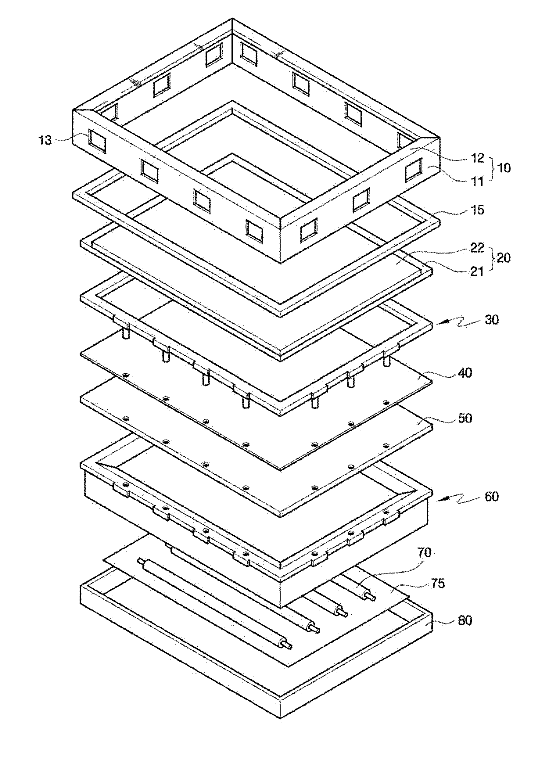
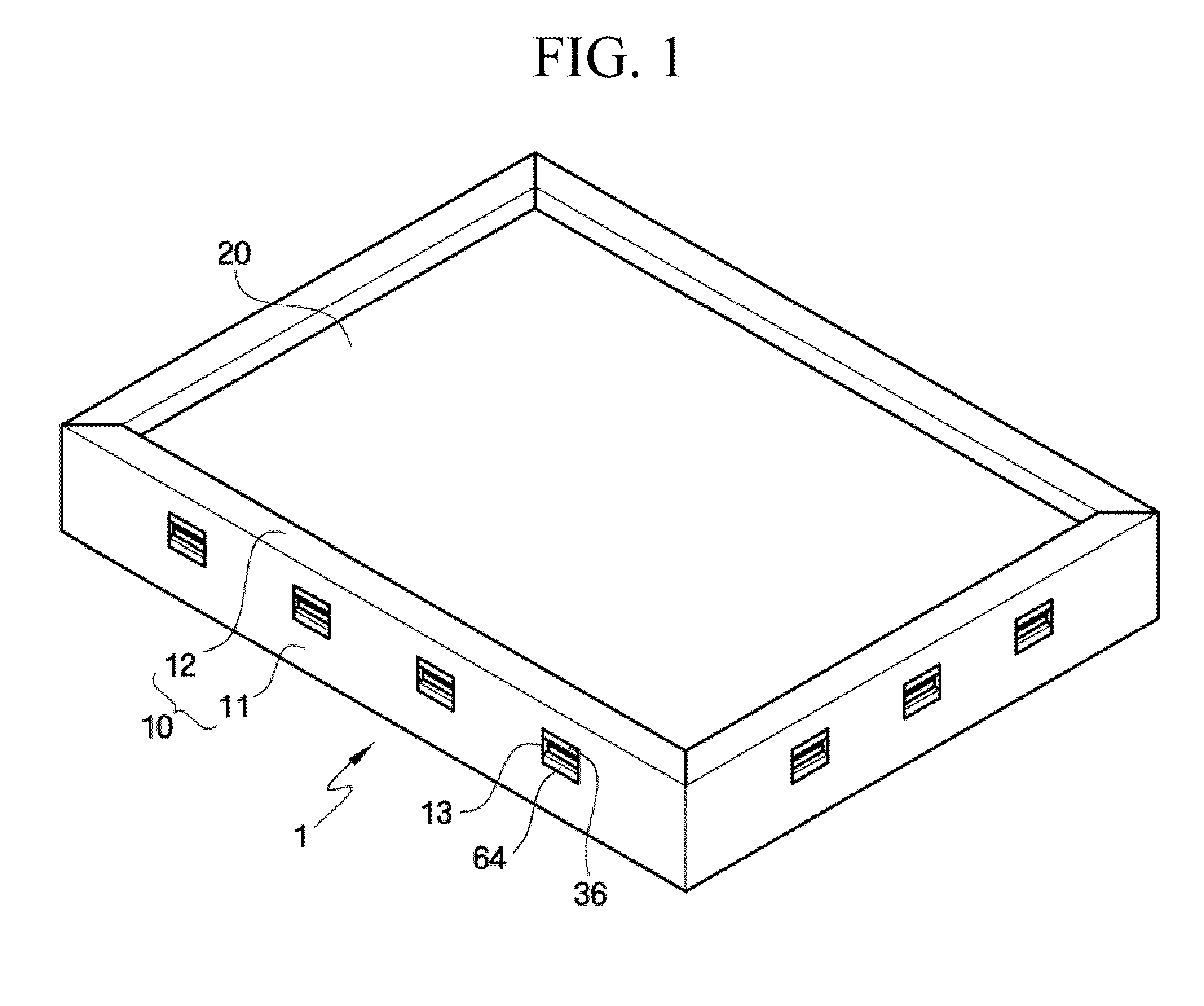
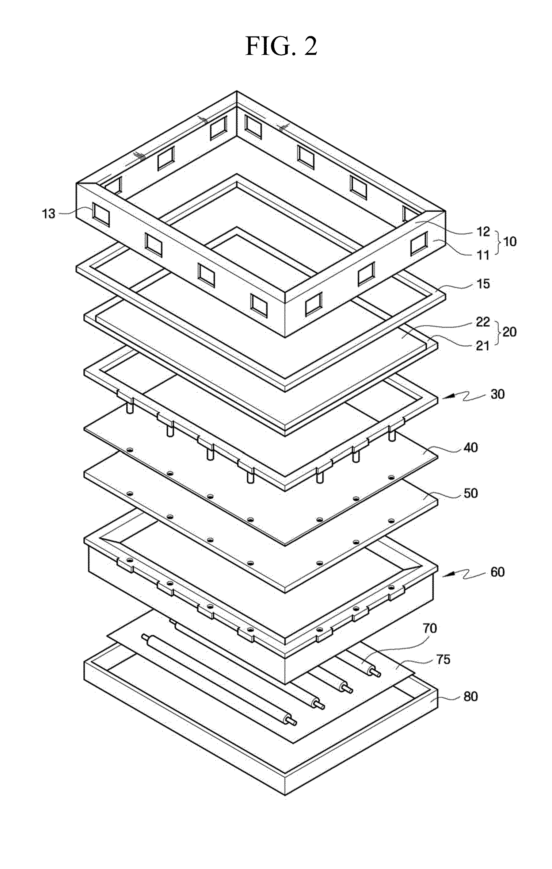
[0030]A display device 1 according to the present invention includes a display panel 20 to display an image, and a backlight assembly to provide light to the display panel 20. The display panel 20 and the backlight assembly are received in an upper receptacle 10 and a lower receptacle 80. In the center part of the upper receptacle 10, an open window for exposing the display panel 20 therethrough is formed. The upper receptacle 10 is formed to increase the exposed area of the display panel 20 to a maximum while maintaining the stiffness enough to maintain the frame of the display device 1. Hereinafter, the structure of the display device 1 will be described in detail.

[0031]The display panel 20 serves to display an image, and includes a lower substrate 21, an upper substrate 22, and a liquid crystal layer (not illustrated) interposed between the two substrates 21 and 22. The lower substrate 21 may include gate lines (not illustrated), data lines (not illustrated), a thin film transist...

second embodiment

[0064]A display device 1 according to the present invention includes a second fixing projection 65 formed on the second frame 60′ to facilitate the assembling of the optical sheet 40 and the diffusion plate 50.

[0065]The first frame 30 forms seating surfaces of the display panel 20. The first frame 30 includes the first fixing projection 31, and fixes the optical sheet 40 and the diffusion plate 50. The first frame 30 may be in the form of a tetragon having an open center part that forms an inner side surface thereof so that the first frame 30 overlaps the edge of the display panel 20. The first frame 30 includes the first fixing projection 31 formed on the lower part thereof. The first fixing projection 31 penetrates the first hole 41 formed on the optical sheet 40 and the second hole 51 formed on the diffusion plate 50, and is inserted into a fixing hole 63 of the second frame 60′. The first fixing projection 31 serves to fix the first frame 30 and the second frame 60′ to each othe...

third embodiment

[0073]A display device 1 according to the present invention includes a reinforcement part 16 reinforcing the stiffness of the bezel part 12′ of the upper receptacle 10′, and the first frame 30′ and the second frame 60 are in hook engagement with each other.

[0074]The first frame 30′ forms seating surfaces of the display panel 20. The first frame 30′ includes the first fixing projection 31, and fixes the optical sheet 40 and the diffusion plate 50. The first frame 30′ may be in the form of a tetragon having an open center part that forms an inner side surface thereof so that the first frame 30′ overlaps the edge of the display panel 20. The first frame 30′ includes the first fixing projection 31 formed on the lower part thereof. The first fixing projection 31 penetrates the first hole 41 formed on the optical sheet 40 and the second hole 51 formed on the diffusion plate 50, and is inserted into a fixing hole 63 of the second frame 60. The first fixing projection 31 serves to fix the f...


PUM


Abstract

A display device according to an embodiment has a structure capable of minimizing the width of a bezel part so that a plurality of display devices may be connected together to constitute a multi-display device. The display device includes a display panel displaying an image; a first frame having an upper surface on which the display panel is seated and a lower surface including first fixing projections; and a second frame engaged with the first frame and including fixing holes into which the first fixing projections are inserted.

Description

CROSS-REFERENCE TO RELATED APPLICATIONS[0001]This application is based on and claims priority from Korean Patent Application No. 10-2009-0005673 filed on Jan. 22, 2009, in the Korean Intellectual Property Office, the disclosure of which is incorporated herein in its entirety by reference.BACKGROUND[0002]1. Technical Field[0003]Embodiments of the present invention generally relate to a display device and, more particularly, to a display device having a structure that may minimizes the width of a bezel part so that a plurality of display devices may be connected together to constitute a multi-display device.[0004]2. Related Art[0005]With the development of modern society as an information society, large-sized and thin display devices are in demand in the market. Since conventional CRT devices cannot fully satisfy such demand, calls for flat display devices represented, for example, by a plasma display panel (PDP), a plasma address liquid crystal display panel (PALC display panel), a l...

Claims


Application Information

Patent Timeline
Patent Type & Authority Applications(United States)
IPC IPC(8): H05K7/00
CPCG02F1/133308G02F2001/133317G02F2001/133322G02F2201/465G02F1/133317G02F1/133322
Inventor OH, YOUNG-ROKKIM, WON-SEOK
Owner SAMSUNG DISPLAY CO LTD
Why Eureka
Try Eureka