Polarized diffractive backlight

a diffractive backlight and polarization technology, applied in the field of backlights, can solve the problems of poor off-axis performance and absorption loss in the film, low polarization ratio te/tm, and low db

Active Publication Date: 2010-12-02
SHARP KK
View PDF13 Cites 61 Cited by
  • Summary
  • Abstract
  • Description
  • Claims
  • Application Information

AI Technical Summary

Benefits of technology

[0032]According to still another aspect, the first major face including the extraction feature structure and the second major face includes a first quarter wave plate layer that rotates the phase of light incident thereon from within the lightguide structure without disrupting total internal reflection.

Problems solved by technology

Commercially available versions typically produce a TE / TM ratio of approximately 3, limited by poor off-axis performance and absorption losses in the film.
However, polarization ratio TE / TM is not as high as “DBEF” films.
Design is expensive and difficult to manufacture.
The design is expensive and very sensitive to the angle of incidence.

Method used


Image

  • Polarized diffractive backlight
  • Polarized diffractive backlight
  • Polarized diffractive backlight

Examples


first embodiment

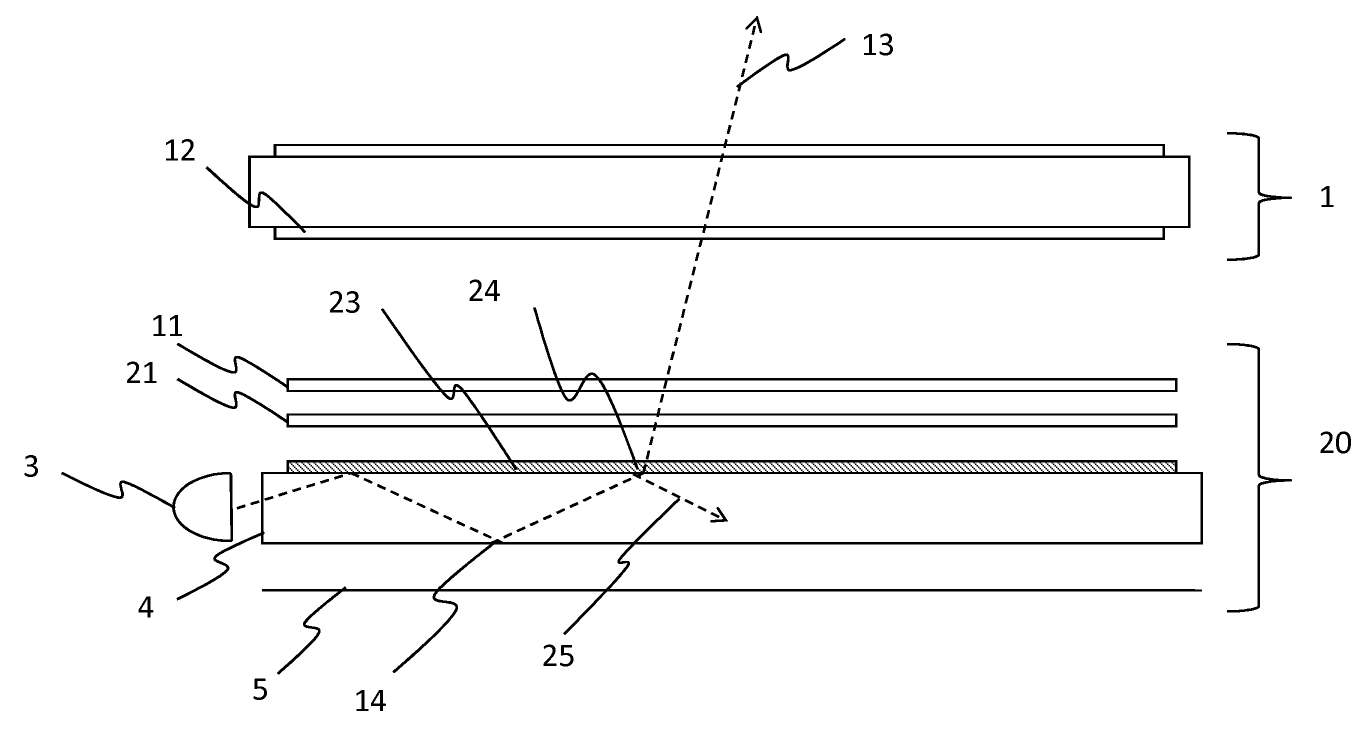
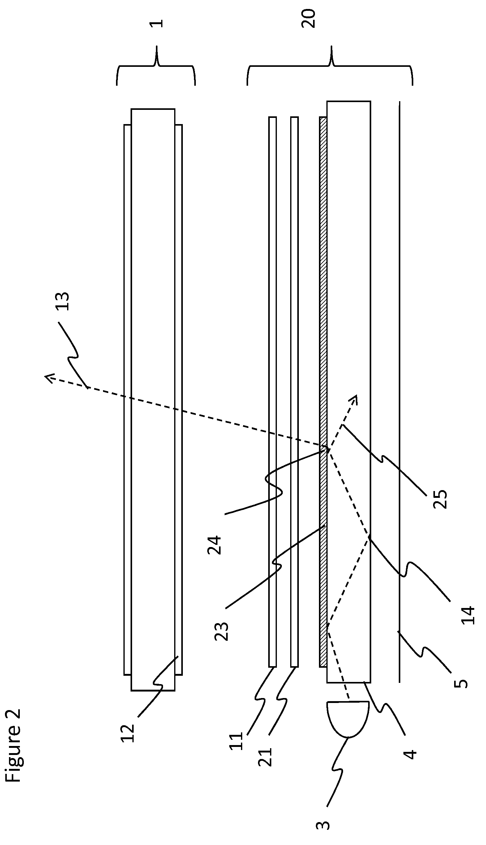
[0061]An overview of the present invention is shown in FIG. 2.

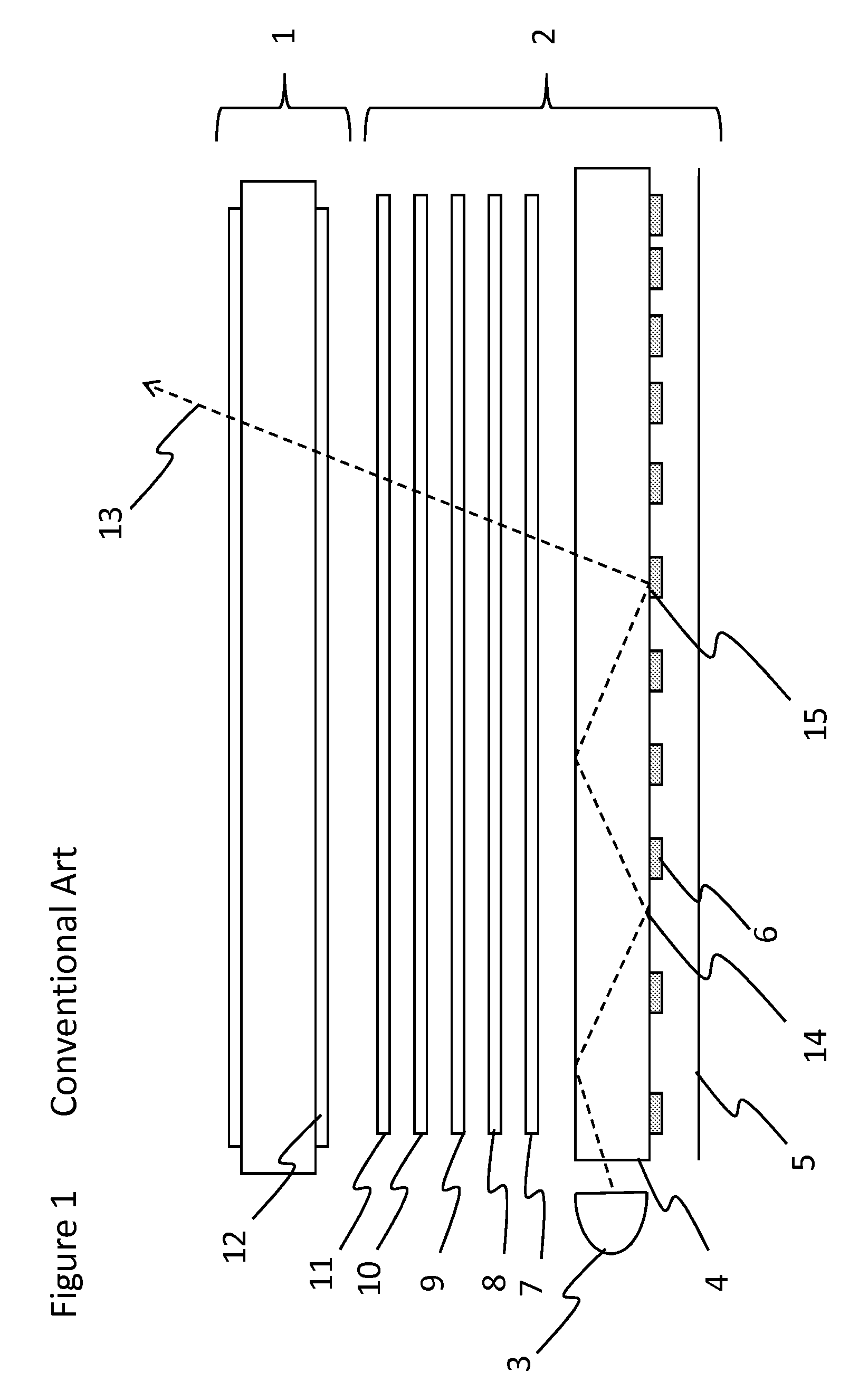
[0062]The first embodiment of the present invention includes a backlight 20 that will be described in reference to the conventional backlight 2 of FIG. 1 and the relevant changes only will be described here.

[0063]As is shown in FIG. 2, the device in accordance with the invention includes a liquid crystal spatial light modulator (SLM) 1 and a backlight 20. The backlight includes a light source 3, a lightguide 4, and a reflector 5. Two sheets, a weak diffuser 21 and a polarization conversion film 11, are individually possible but not required in this arrangement. The lightguide 4 has sub-wavelength extraction features 23 that can be positioned on one or both major faces of the lightguide 4. In this example, the extraction features 23 are on the top surface.

[0064]Light 22 in the lightguide 4 is transmitted to the extraction features by TIR 14 and extracted at the surface 24 by the extraction features 23. The form of these ex...

second embodiment

[0072]the present invention is shown in FIG. 4. For sake of brevity, only the relevant differences between this embodiment and the embodiment of FIG. 2 are described herein.

[0073]In this aspect the lightguide 4 of the backlight 40 has a second layer 41, in which the refractive index of this layer 41 is less than that of the lightguide 4. The diffractive features 23 are placed on the second layer 41. In this arrangement the range of angles in the second layer 41 is much reduced. This means the quality of the out-coupled light is significantly improved over the single-lightguide approach.

[0074]Extraction of light at 42 from the main lightguide 4 into the secondary lightguide formed by the second layer 41 can be controlled by appropriate non-diffractive features on the opposite face of the lightguide 4, for example shallow wedge shaped features 48 that redirect at 47 a small proportion of the lightguide light 45 into the second layer 41.

[0075]The number of such additional layers is not...


PUM


Abstract

A backlight is provided for illuminating an at least partially transmissive display. The backlight includes a light source. A light guide receives the light from an edge surface and guides the light by total internal reflection. The light is extracted from the lightguide using sub-wavelength extraction features designed on the basis of two interleaved grating structures. The emitted light, using this arrangement has a high level of polarization.

Description

TECHNICAL FIELD [0001]The present invention relates to a backlight, for example for use with an at least partially transmissive spatial light modulator. The present invention also relates to a display including such a backlight. More particularly, the present invention relates to a distributed illumination panel that may be used for general illumination.BACKGROUND OF THE INVENTION [0002]FIG. 1 of the accompanying drawings illustrates the stack structure of a typical liquid crystal display (LCD) module of small size, for example for a mobile phone or PDA device. The display includes a flat transmissive spatial light modulator (SLM) in the form of an LCD panel having input and output polarizers on its bottom and top sides. The rest of the structure is generally regarded as the backlight system, as follows. A light source (for example an LED or Laser) emits light, which is coupled into a lightguide and distributed across the back of the display by way of total internal reflection (TIR)...

Claims


Application Information

Patent Timeline
Patent Type & Authority Applications(United States)
IPC IPC(8): F21V7/04G02B6/00G02B5/30
CPCG02B6/0036G02B6/0038G02B6/0056G02B6/0076G02F1/13362
Inventor PAPAKONSTANTINOU, IOANNISMONTGOMERY, DAVID JAMES
Owner SHARP KK
Why Eureka
Try Eureka