Robust Routing of Data in Wireless Networks

Inactive Publication Date: 2010-12-02
UNIV COLLEGE CORK NAT UNIV OF IRELAND CORK
View PDF7 Cites 20 Cited by
  • Summary
  • Abstract
  • Description
  • Claims
  • Application Information

AI Technical Summary

Benefits of technology

[0023]In one embodiment, at least some nodes comprise means for maintaining a link-break counter and at least some nodes are adapted to automatically perform topology re-build if the

Problems solved by technology

However, experiments show that wireless networks have a high fluctuation in link quality.
Links might become frequently unavailable (or available) for longer time periods.
Therefore it is impossible to build a stable routing topology.
Again, it is impossible to obtain a constant routing topology.
However, due to the wireless channel characteristics (e.g. interferences), a link between two nodes used in the tree might become (temporarily) unavailable.
Hence, data forwarding to the base st

Method used


Image

  • Robust Routing of Data in Wireless Networks
  • Robust Routing of Data in Wireless Networks
  • Robust Routing of Data in Wireless Networks

Examples


Embodiment Construction

Brief Description of the Drawings

[0032]The invention will be more clearly understood from the following description of some embodiments thereof, given by way of example only with reference to the accompanying drawings in which:—

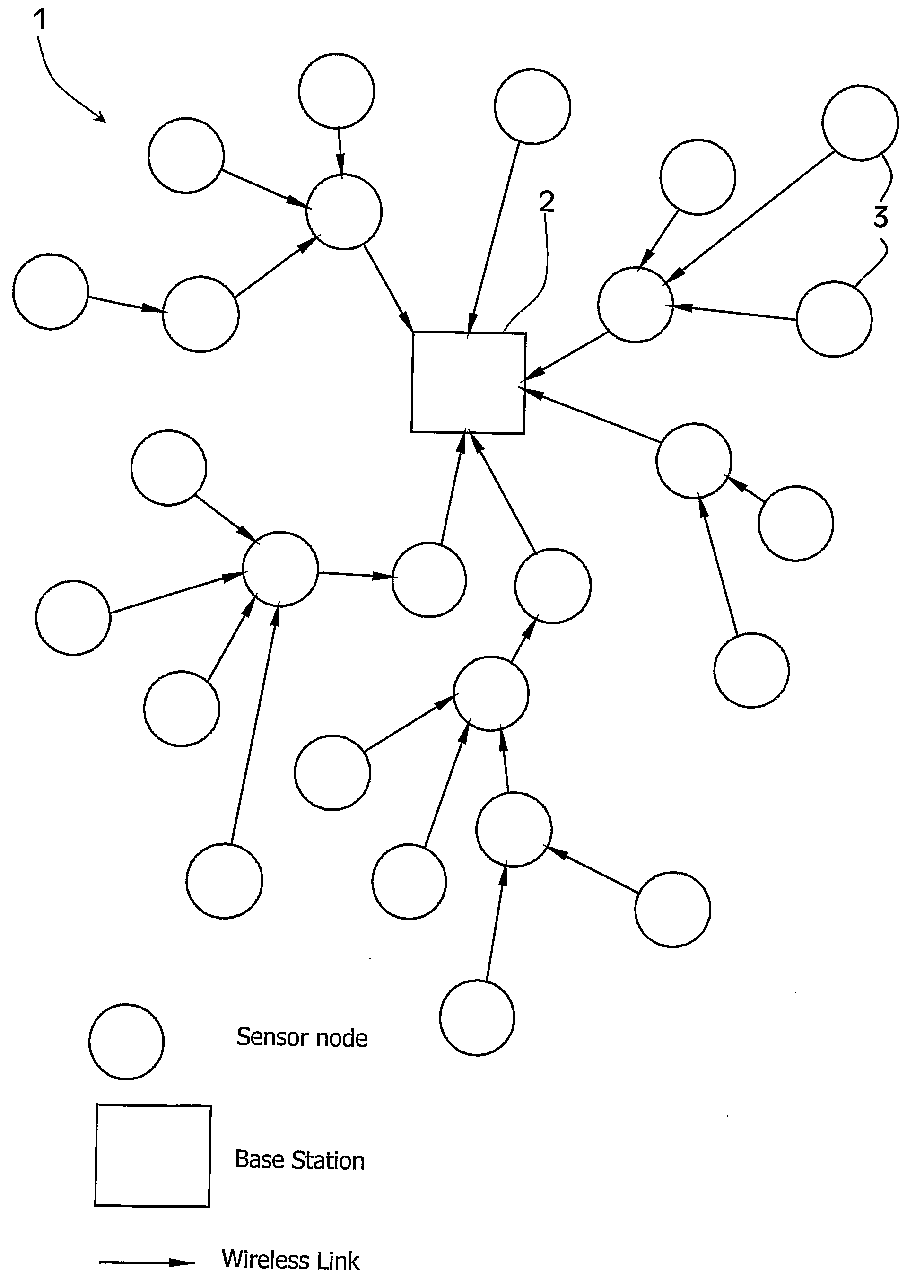
[0033]FIG. 1 illustrates a sensor network;

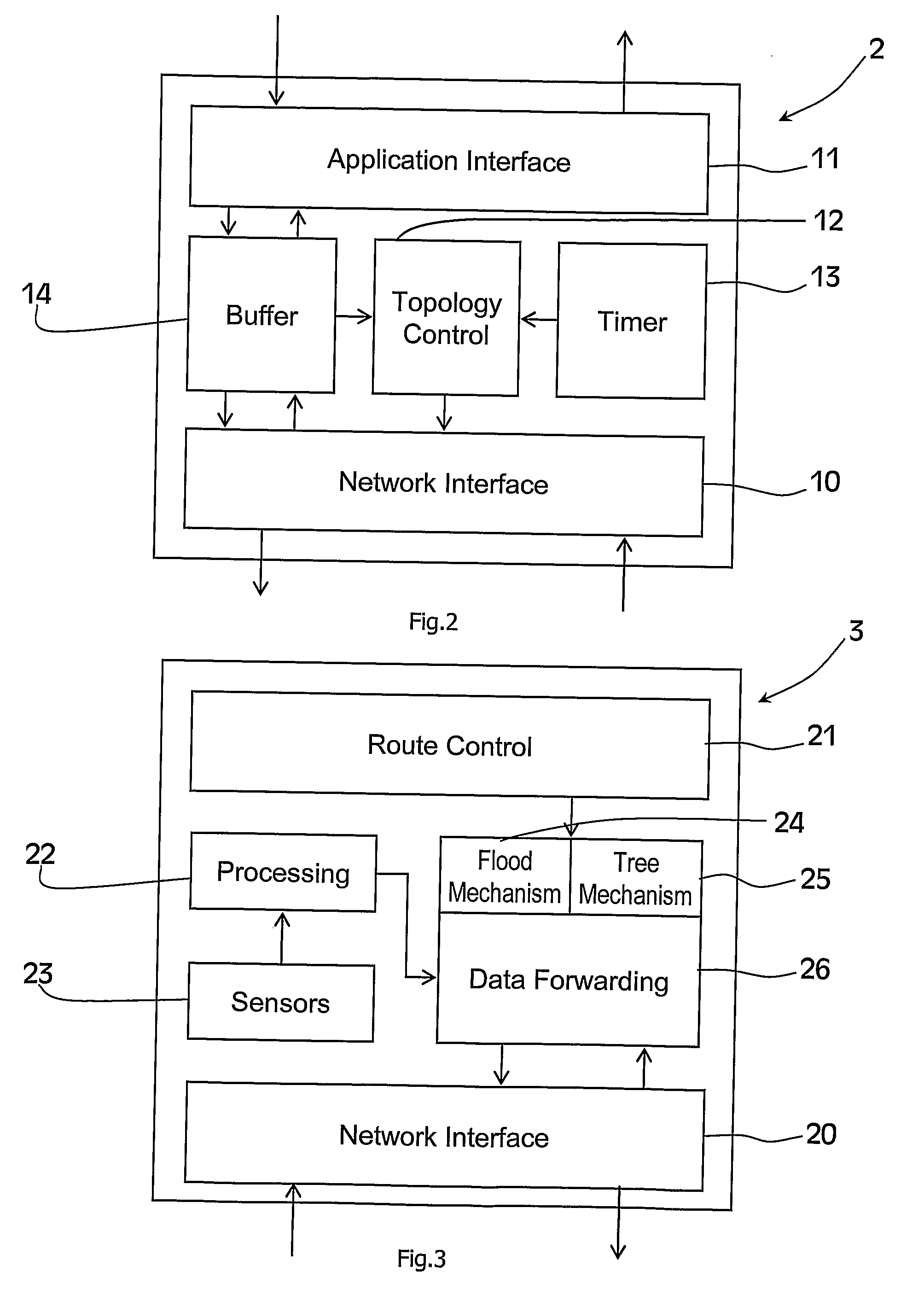
[0034]FIG. 2 illustrates base station components;

[0035]FIG. 3 shows sensor node components;

[0036]FIG. 4 is a flow diagram illustrating base station operation;

[0037]FIG. 5 illustrates flow for receiving a topology discovery message;

[0038]FIG. 6 illustrates flow for receiving a topology discovery message with local rebuild enabled.

[0039]FIG. 7 illustrates flow for receiving a sensor message with lateral transmission enabled;

[0040]FIG. 8 illustrates receiving a sensor message with both lateral transmission and local rebuild enabled; and

[0041]FIG. 9 illustrates flow for forwarding sensor messages.

DESCRIPTION OF THE EMBODIMENTS

[0042]Referring to FIG. 1 a wireless network 1 comprises a base station 2 and sensor nodes 3. Wir...


PUM


Abstract

A wireless network (1) comprises a base station (2) and sensor nodes (3). The base station (2) comprises a network interface (10), an application interface (11), topology control functions (12) a timer (13), and a buffer (14). Each sensor node (3) comprises a network interface (20), route control functions (21), processing functions (22), sensors (23), flood mechanism programs (24), tree mechanism programs (25), and data forwarding programs (26). The network operates by establishing a conventional routing tree from the sink node that is used when the network is stable. But when a sending node detects a node or link failure it dynamically switches to sending its data packets using a flooding mechanism, rather than waiting for the routing tree to be reestablished. This reduces the latency for data delivery. Also, when flooding the data packets, it allows the packets to be flooded to nodes that are an equal number of hops from the sink node as the send node is from the sink node. This approach is suitable in situations where an obstacle causes the path between the sending node and the sink to be blocked, thus requiring a strategy in which packets are routed by less direct means. It increases the probability of delivery.

Description

INTRODUCTION[0001]1. Field of the Invention[0002]The invention relates to routing of data such as sensor data in wireless networks.[0003]2. Prior Art Discussion[0004]In many wireless sensor networks data is generated by the nodes and has to be forwarded to a given base-station. Generally, data is forwarded in a hop-by-hop fashion as nodes cannot communicate directly with the base-station. A “routing mechanism” is used to decide on which path(s) to use. The routing mechanism itself forms and uses a network topology which is constrained by the available communication links between nodes.[0005]Most available routing mechanisms assume stable links between nodes. However, experiments show that wireless networks have a high fluctuation in link quality. Links might become frequently unavailable (or available) for longer time periods. The following two examples show conditions in which such link quality fluctuation is experienced.[0006]A sensor network is used to monitor car park spaces, in...

Claims


Application Information

Patent Timeline
IPC IPC(8): H04J3/14H04L45/02
CPCH04L45/021H04L45/28H04L45/32H04W40/14H04W40/24H04W40/26H04W84/18H04L41/0654H04L45/02
Inventor SREENAN, CORMAC J.BENSON, JONATHANROEDIG, UTZ
Owner UNIV COLLEGE CORK NAT UNIV OF IRELAND CORK
Why Eureka
Try Eureka