Dual-Layer Beam Forming in Cellular Networks
- Summary
- Abstract
- Description
- Claims
- Application Information
AI Technical Summary
Problems solved by technology
Method used
Image
Examples
first embodiment
[0066]In a first embodiment, a one bit flag of SU / MU switching is explicitly included in each DL grant. This bit indicates that the corresponding PDSCH are for a single user (SU) or for two users (MU).
[0067]The transport block to codeword mapping is signaled by one bit in the DL grant, and an explicit fixed mapping between codeword to DMRS layer is assumed, i.e., codeword 1 is transmitted on DMRS layer 1 and codeword 2 is transmitted on DMRS layer 2. If SU-MIMO is detected (1-bit in PDCCH), the relationships between the transport blocks and the DMRS layers are clearly defined.
[0068]In the case of MU-MIMO, rank-1 single-layer is received by each UE. Signaling the index to the DMRS layer may not be needed. The index to the DMRS layer may be implicitly derived in the following manner as listed in Table 3.
TABLE 3Derivation of index to DMRS layer from rank indicator (RI)for MU-MIMO dual layer beamforming with dynamic switchingSU / MURITwo TBSsInterpretationSURI = 1Enabled,CleardisabledSURI...
second embodiment
[0070]In a second embodiment, SU / MU switching may be explicitly signaled by other approaches, e.g., masking the CRC of the PDCCH with different scrambling sequences. For example, scrambling sequence 1=UE shall receive both transport blocks (SU-MIMO). Scrambling sequence=0 means UE should receive only one transport block (MU-MIMO).
[0071]In this case, the interpretation of DMRS layer, presence of the co-scheduled UE, MCS of the co-scheduled UE can be similarly obtained as in Table 3. Index of the DMRS layer may be either derived with RI+TBS enabling / disabling configuration as in Table 3, or explicitly signaled in DL grant.
third embodiment
[0072]In a third embodiment, it is also possible to apply more scrambling sequences to the PDCCH CRC to further differentiate the index of the DMRS layer that a UE will use to demodulate PDSCH when configured in SU-MIMO transmission. However, this reduces the UE-ID space and negatively impacts the system capacity.
[0073]In other embodiments of the invention, for dynamic SU / MU mode with the same PDCCH format, some information may also be implicitly signaled by different masking of the CRC of the PDCCH with different scrambling sequences. This includes: presence of a co-scheduled UE, indexing to the DMRS layer, SU / MU-MIMO mode, or combinations of the above.
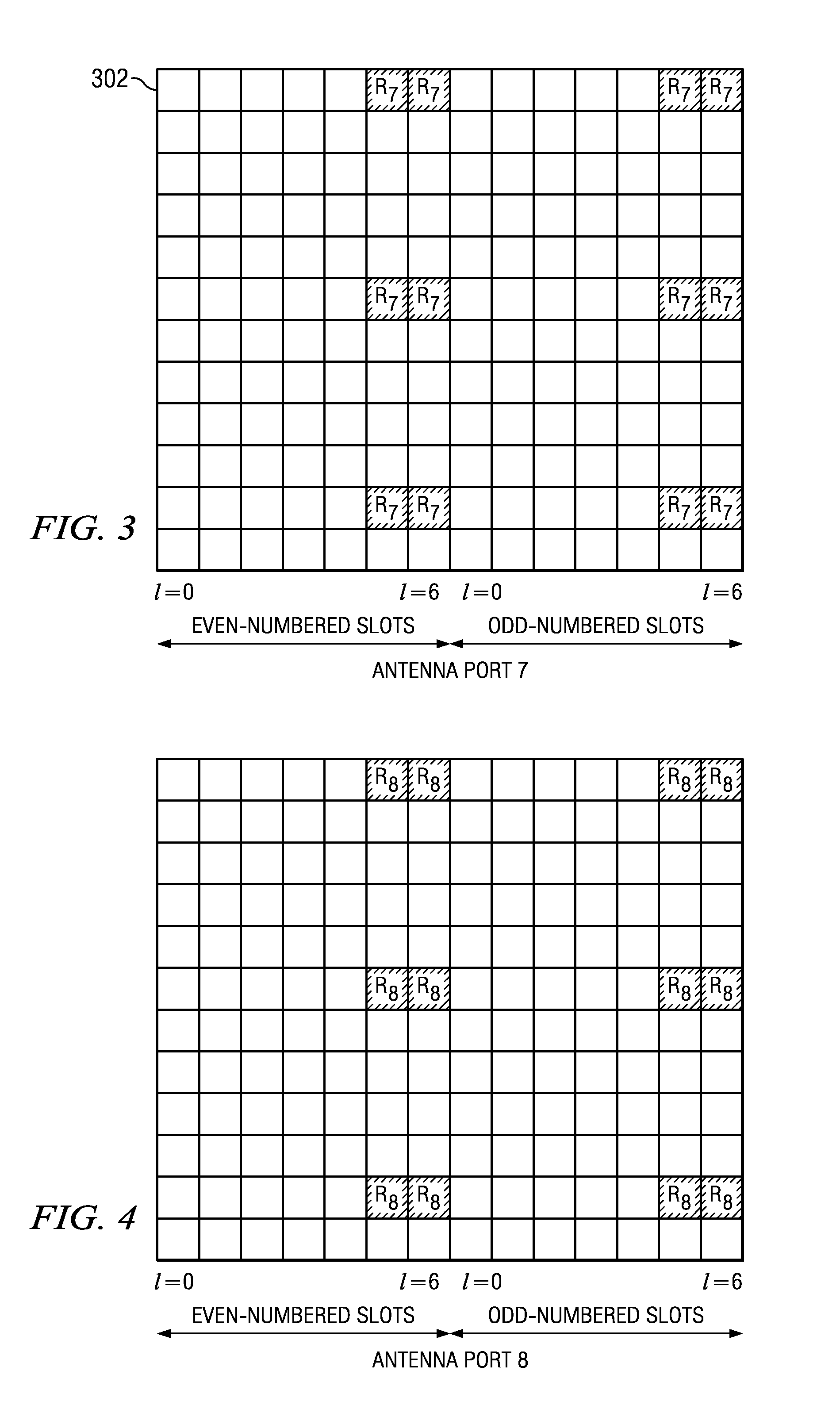
[0074]An embodiment of the invention is specified in 3rd Generation Partnership Project; Technical Specification Group Radio Access Network; Evolved Universal Terrestrial Radio Access (E-UTRA); Physical Channels and Modulation (Release 9) 3GPP TS 36.211 V9.1.0 (2010-03)), section 6.3.3.4. Spatial multiplexing using antenna ports with...
PUM
 Abstract
Description
Claims
Application Information
 - R&D
- Intellectual Property
- Life Sciences
- Materials
- Tech Scout
- Unparalleled Data Quality
- Higher Quality Content
- 60% Fewer Hallucinations
Browse by: Latest US Patents, China's latest patents, Technical Efficacy Thesaurus, Application Domain, Technology Topic, Popular Technical Reports.
© 2025 PatSnap. All rights reserved.Legal|Privacy policy|Modern Slavery Act Transparency Statement|Sitemap|About US| Contact US: help@patsnap.com


