
Configuring Power Distribution Within Cooperation Areas of Cellular Communication Networks

a technology power distribution, applied in the field of cellular communication network, can solve the problems of inability to achieve, practicable inability, and interference, and achieve the effect of reducing interference, less power, and more power

Active Publication Date: 2014-02-27
NOKIA SOLUTIONS & NETWORKS OY
View PDF7 Cites 244 Cited by
  • Summary
  • Abstract
  • Description
  • Claims
  • Application Information

AI Technical Summary

Benefits of technology

This patent talks about a way to improve the performance of a cellular network by making the power distribution in a specific area more effective. This is done through a technique called beamforming, which allows for directional signal transmission or reception. By using adapted or fixed receive / transmit beampatters and configuring the power level accordingly, interference at the edges of the network can be reduced. Additionally, by dividing the available frequency band into subbands and scheduling almost all users in the network as center users, interference between neighboring base stations can be minimized. Overall, this approach can lead to better network performance and improved user experience.

Problems solved by technology

Between neighbouring cooperation areas, interferences may occur, especially in edge regions of the cooperation areas (CAs).
Full network wide cooperation would overcome the interference floor completely, but is practically infeasible.

Method used


Image

  • Configuring Power Distribution Within Cooperation Areas of Cellular Communication Networks
  • Configuring Power Distribution Within Cooperation Areas of Cellular Communication Networks
  • Configuring Power Distribution Within Cooperation Areas of Cellular Communication Networks

Examples


Embodiment Construction

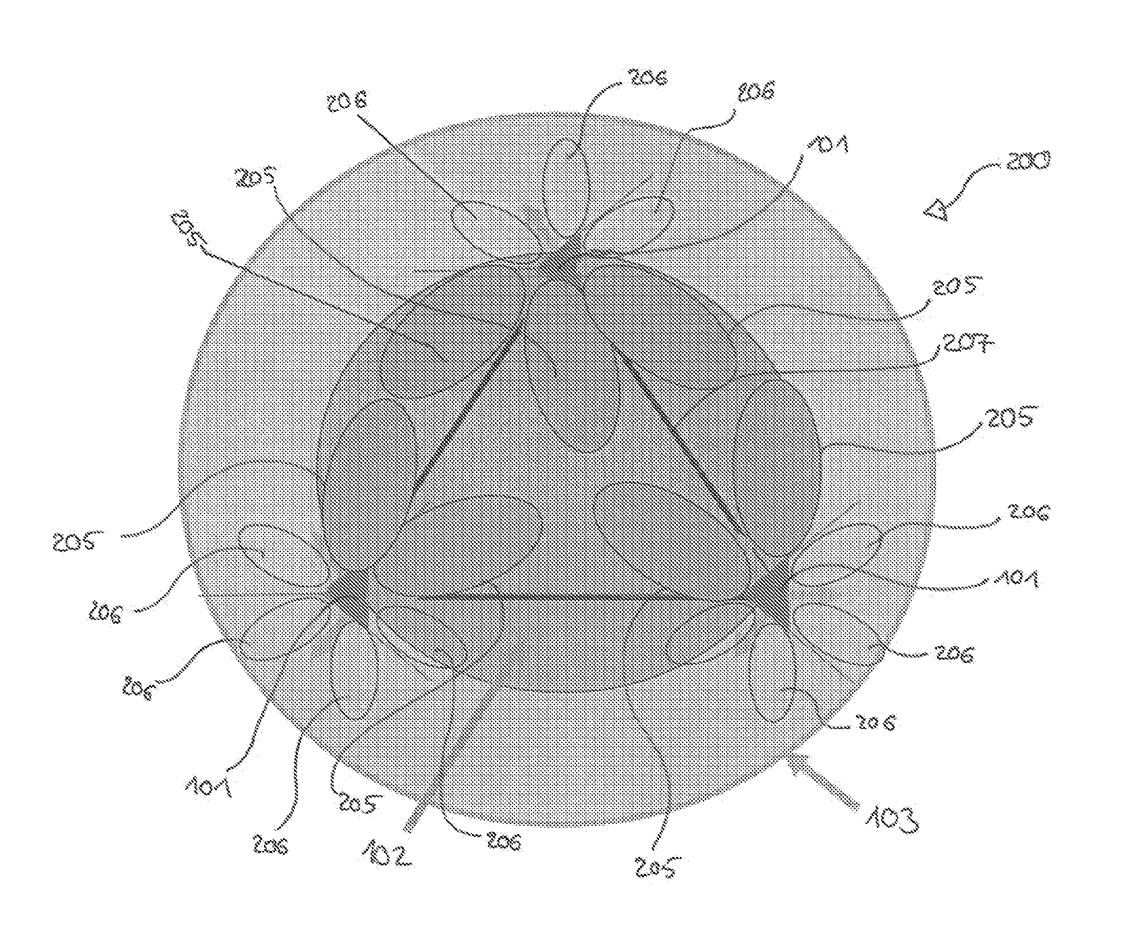
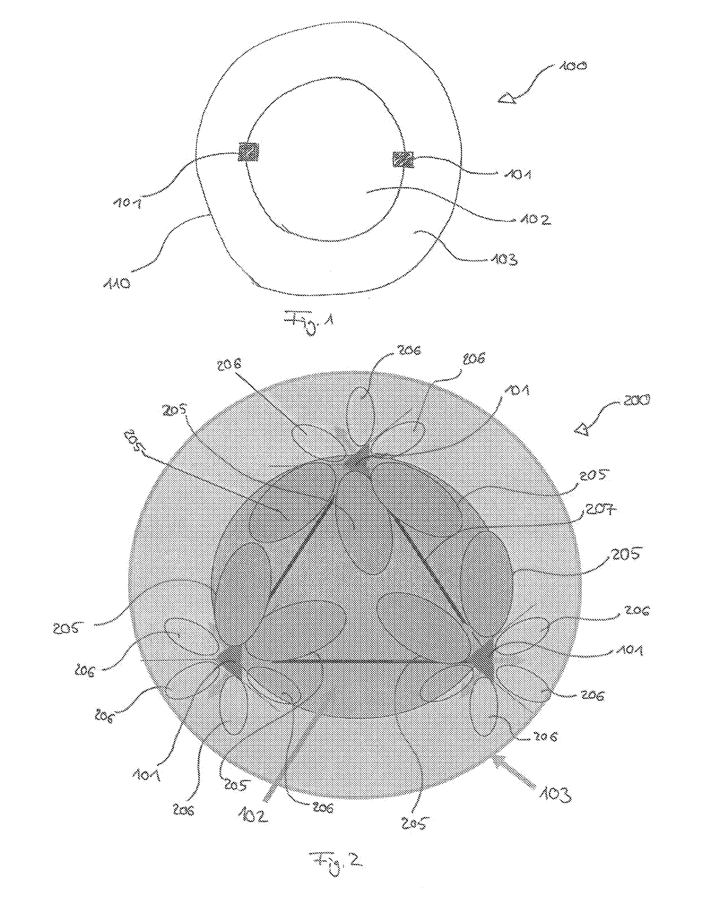
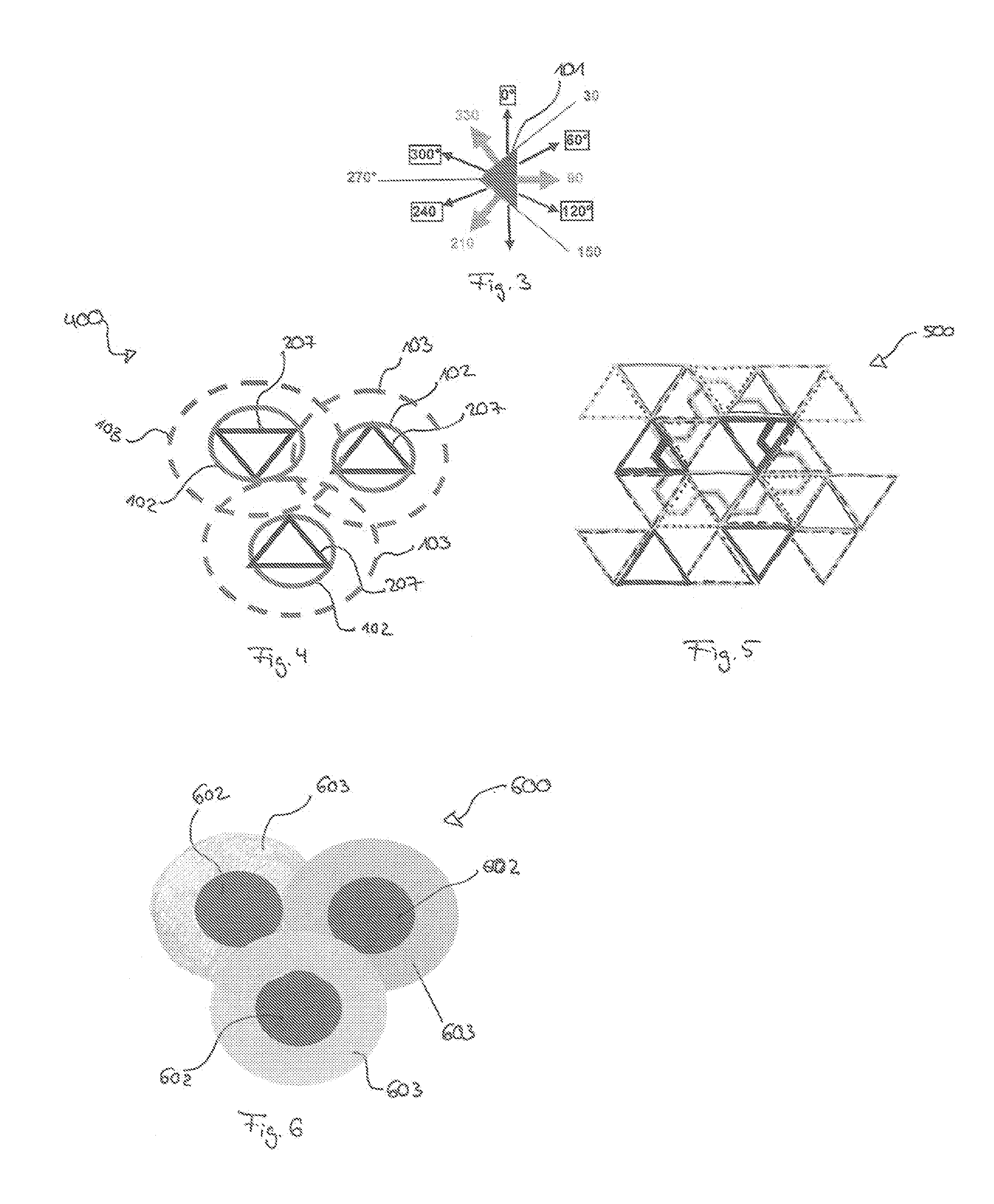
[0060]The illustration in the drawings is schematic. It is noted that in different figures, similar or identical elements are provided with the same reference signs or with reference signs, which are different from the corresponding reference signs only within the first digit.

[0061]In the following, embodiments of the herein disclosed subject matter are illustrated with reference to the drawings and reference to aspects of current standards, such as LTE. However, such reference to current standards is only exemplary and should not consider as limiting the scope of the claims.

[0062]Embodiments of the herein described subject matter lie in the field of mobile radio system concepts like LTE, LTE-A and its evolution. Such systems may deal with the case of joint precoding coordinated multi point (JP-CoMP) transmission. There has been a CoMP study item (SI) for LTE Rel 10, but without clear conclusion a remarkable system level gain could be found only for very complex system setups. A new...


PUM


Abstract

There is provided a method for configuring a power distribution within a cellular network system. The cellular network system includes at least one cooperation area. The at least one cooperation area is defined by at least two base stations, each including at least one antenna, wherein each base station has at least one beam. The method includes configuring the base stations to transmit at a first transmit power level for providing a first receiving power level for a user equipment at a center region of the cooperation area, and configuring the base stations to transmit at a second transmit power level for providing a second receiving power level at a border region of the cooperation area, wherein the second receiving power level is lower than the first receiving power level.

Description

FIELD OF THE INVENTION[0001]The present invention relates to the field of cellular communication networks and in particular to cellular communication networks which are organized in cooperation areas.BACKGROUND OF THE INVENTION[0002]Modern wireless communication networks often are organized in a cell structure. In LTE (3GPPP Long-Term Evolution), cells may be organized in so called cooperation areas. Cooperation areas may be defined by one or more base stations (eNodeBs, eNBs) serving one or more cells. Between neighbouring cooperation areas, interferences may occur, especially in edge regions of the cooperation areas (CAs).[0003]Interference floor reduction is a research issue for a long time, which led to many proposals like inter cell interference cancellation (ICIC), increased antenna tilting, SON optimization algorithms, scheduling, coordinated beamforming, etc. Full network wide cooperation would overcome the interference floor completely, but is practically infeasible.[0004]I...

Claims


Application Information

Patent Timeline
Patent Type & Authority Applications(United States)
IPC IPC(8): H04W52/24
CPCH04W52/243H04B7/024H04W52/283H04W52/40H04W52/42H04W72/12H04W84/18H04W88/08H04W28/04
Inventor ZIRWAS, WOLFGANGMENNERICH, WOLFGANG
Owner NOKIA SOLUTIONS & NETWORKS OY
Learn More