Method and System for Synchronizing a Group of End-Terminals

a technology of end-terminals and synchronization methods, applied in data switching networks, frequency-division multiplexes, instruments, etc., can solve problems such as limited scalability of proposed schemes, unknown delays in packets in the network, and introduction of iptv systems

Active Publication Date: 2010-12-02
KONINK KPN NV +1
View PDF20 Cites 48 Cited by
  • Summary
  • Abstract
  • Description
  • Claims
  • Application Information

AI Technical Summary

Benefits of technology

[0012]providing the first network node and the second network node with the delay information enabling one or more variable delay units in the first and second network node to delay transmission of the stream to end-terminals connected to the first and second network node such that the streams received by the end-terminals are substantially synchronized.
[0047]means for providing the first network node and the second network node with the delay information enabling one or more variable delay units in the first and second network node to delay transmission of the stream to end-terminals connected to the first and second network node such that the streams received by the end-terminals are substantially synchronized.

Problems solved by technology

During transmission of the streams, the packets are subjected to unknown delays in the network such as transmission delays, differences in network routes and differences in coding and decoding delays.
Implementation of such schemes in a typical IPTV system introduces however certain problems.
A first problem relates to the limited scalability of the proposed schemes.
Further, a distributed scheme requires a multitude of multicast channels, which is a limited resource.
A second problem relates to the use of controllable variable-delay buffers in the end-terminals.
These buffers and the additional functionality for receiving and transmitting timing information imply increased costs of the end-terminal and the inability to use legacy terminals that do not have these capabilities.
Moreover, if a user of an end-terminal joins a synchronized group, the local buffering at the end-terminals takes a significant adaptation time before the user is in synchronization with the other end-terminals in the group.

Method used


Image

  • Method and System for Synchronizing a Group of End-Terminals
  • Method and System for Synchronizing a Group of End-Terminals
  • Method and System for Synchronizing a Group of End-Terminals

Examples


Embodiment Construction

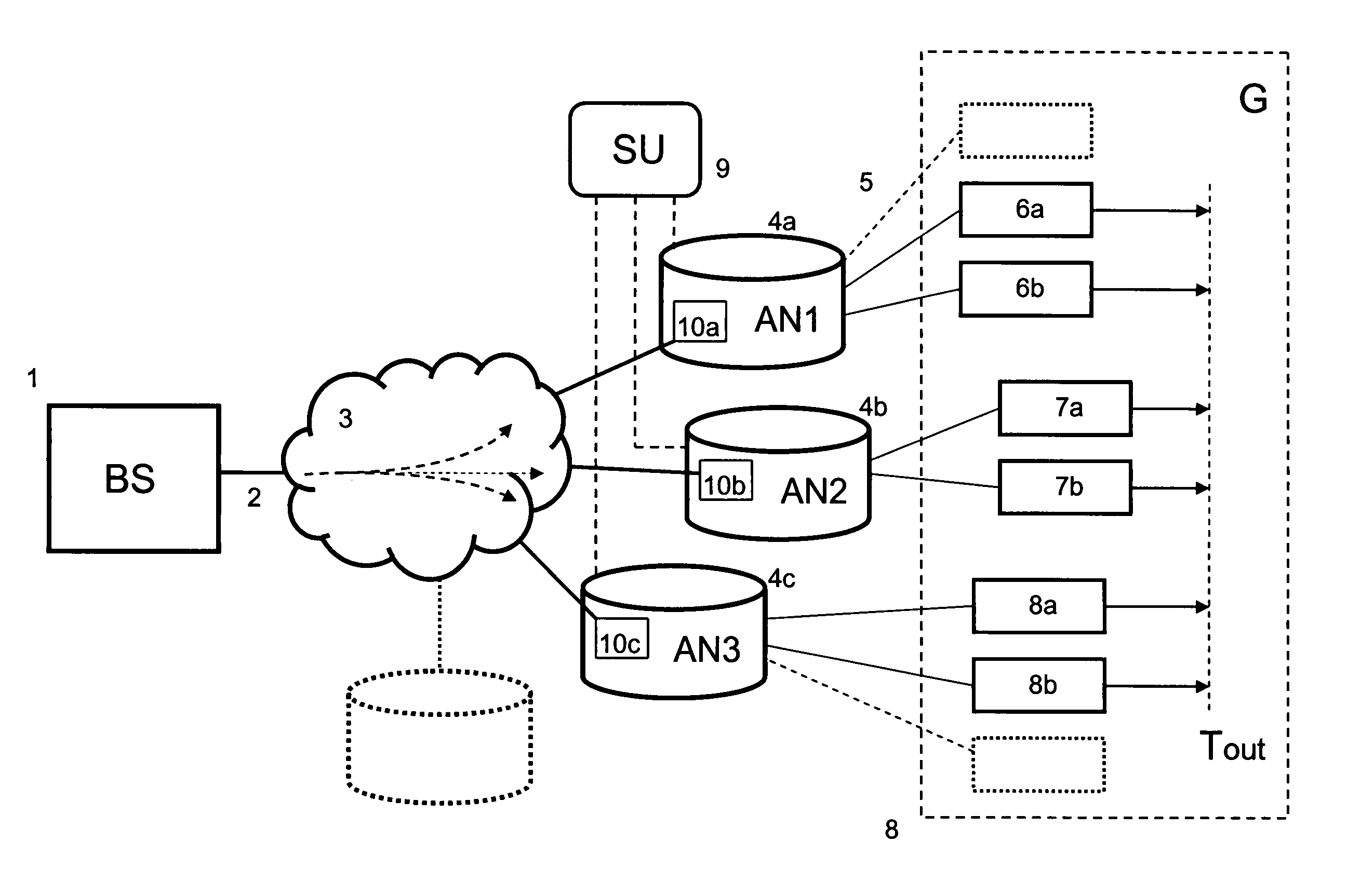
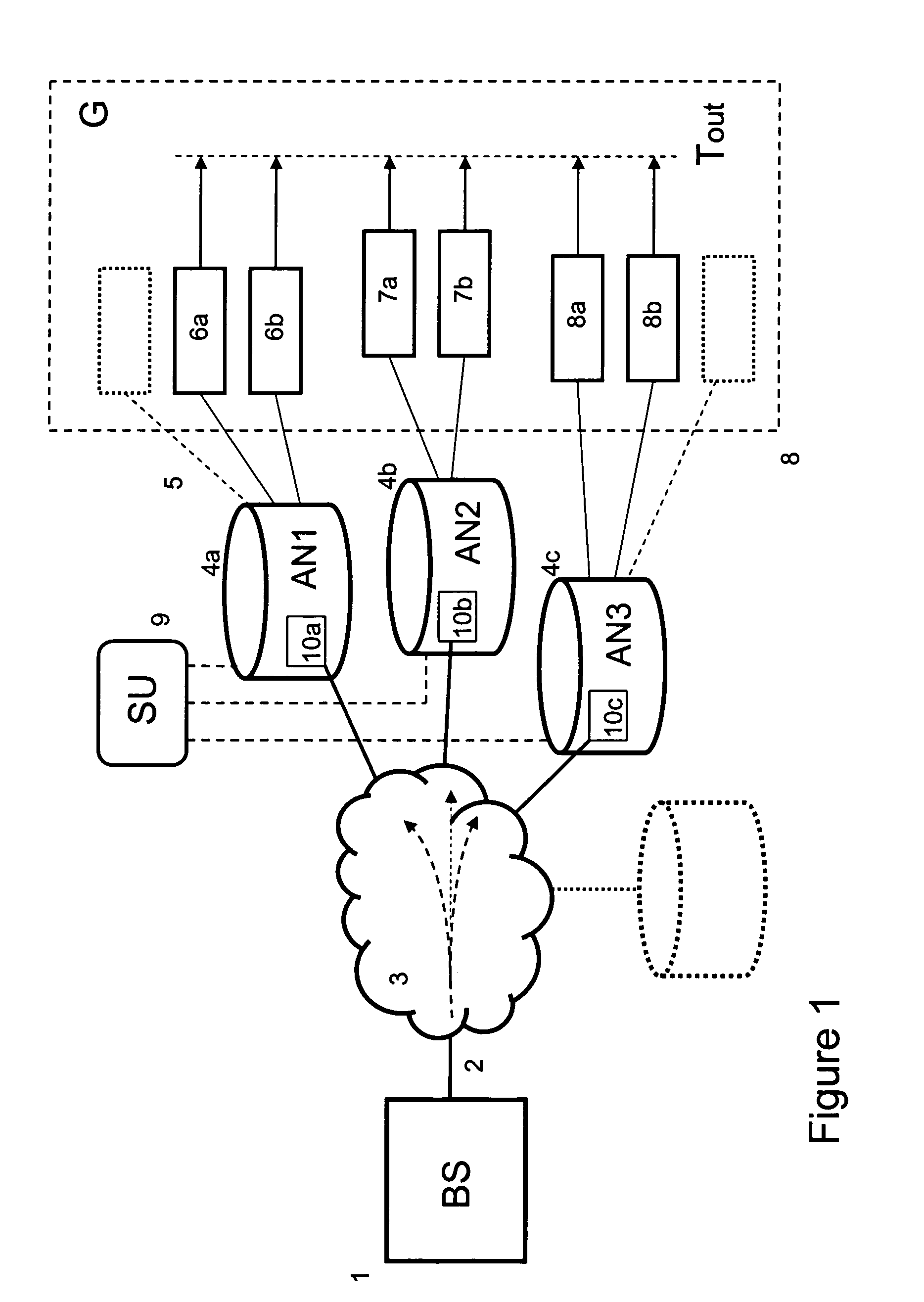
[0064]FIG. 1 illustrates a first system according to the invention. A broadcast station (BS) 1, preferably an IPTV system, e.g. an IPTV system having an IMS-type architecture, transmits a packetized transport stream 2, typically a multicast stream, via a network 3, e.g. a high bandwidth IP network, of an operator to a number of access nodes (AN1, AN2, AN3, . . . ; 4a, 4b, 4c, . . . ).

[0065]The video content in the stream may be compressed using for example MPEG-2 or MPEG-4. Further, the Real-time Transport Protocol (RTP) may be used to stream the IPTV content over the network. The services provided by RTP include sequence numbering, time stamping and delivery monitoring allowing synchronization of the packets in one stream and between associated streams so that consecutive frames in a stream are played at the correct time.

[0066]The access nodes may be an Digital Subscriber Line Access Multiplexer (DSLAM), an Cable Modem Termination System (CMTS), an optical access node or an edge ro...


PUM


Abstract

A method is described for synchronizing the transmission of a stream to a group of end-terminals. The method is used in a system comprising a station transmitting a packetized stream over a network to at least a first and second network node. Each network node comprises a variable delay unit and each network node is connected to one or more end-terminals. In the method the synchronization unit receives arrival time information of a packet in the broadcast stream at the first and second network node. Delay information is calculated for the first and second network node on the basis of the arrival time information of the packet. Further, the delay information is transmitted to the first and second network node so that the variable delay unit in the first and second network node is able to transmit the broadcast stream to the first and second end-terminal in a substantially synchronized way.

Description

FIELD OF THE INVENTION[0001]The invention relates to method and system for synchronizing a group of end-terminals. The invention further relates to a synchronization unit and to a network node for use in such system.BACKGROUND OF THE INVENTION[0002]New multi-media techniques such as Voice over IP (VoIP) and Internet Protocol Television (IPTV) open a whole range of new multi-media services. One type of these services enable a group of users to separately watch the same TV channel and communicate with each other using text, audio and / or video. Such services require that the output signal of the end-terminals is transmitted at the same time to all users in the group. In other words, the outputs of the display devices in the group, e.g. televisions, PDAs, mobile devices, PCs or a combination thereof, should be synchronized.[0003]In an IPTV system the TV channel signal is typically transmitted as one or more packetized streams over an high-bandwidth IP network of an operator via network ...

Claims


Application Information

Patent Timeline
Patent Type & Authority Applications(United States)
IPC IPC(8): H04J3/06
CPCH04L65/80H04L65/4076H04L65/611
Inventor NIAMUT, OMAR AZIZVAN DEVENTER, MATTIJS OSKARSTOKKING, HANS MAARTENWALRAVEN, FABIAN ARTHUR
Owner KONINK KPN NV
Why Eureka
Try Eureka