System and Method for Conducting Multiplexed Electrical Impedance Tomography

a technology of electrical impedance tomography and system, which is applied in the field of system and method for conducting multiplexed electrical impedance tomography, can solve the problems of difficult to achieve in practice, and inability to achieve frame rates in excess of 100 frames/second,

Inactive Publication Date: 2010-12-02
UNIVERSITY OF CAPE TOWN +1
View PDF9 Cites 23 Cited by
  • Summary
  • Abstract
  • Description
  • Claims
  • Application Information

AI Technical Summary

Benefits of technology

[0014]It is an object of this invention to provide a system and method for conducting multiplexed electrical impedance tomography that enables images to be generated at a speed that is superior to that practically associated with commercial systems presently available and of which applicants are aware.

Problems solved by technology

Taking a frame of EIT data using sequential measurements (so-called time-division multiplexed or TDM measurements) is slow, so that frame rates in excess of 100 frames / second are extremely difficult to achieve.
A basic constraint in EITS frame rate is imposed by the lower limit of spectral bandwidth; for example, if the impedance at 20 Hz is required, the frame rate per second will be limited to 20 / k, where k is the number of sequential measurements required per frame; and even this limit implies sampling only a single cycle of the lowest frequency per measurement, which is somewhat difficult to achieve in practice.
Use in the past has thus been limited, for example to EIT imaging of fast electrical and slow blood flow related changes during functional activity and epilepsy.
A number of problems are encountered in FDM EIT as a consequence of accommodating simultaneous current injection and voltage measurement on the same electrode.
A second issue is that the current through any terminal must be a sum of orthogonal component currents, and equal and opposite components must flow through some other terminal.
Ensuring that the net current due to each component is zero is electronically complicated, and has not been attempted in any of the FDM EIT systems known to applicant.
These systems have generally avoided these problems by using separate sets of current injection and voltage measurement electrodes, although this has the disadvantage that twice the number of electrodes are required to obtain the same resolution.

Method used


Image

  • System and Method for Conducting Multiplexed Electrical Impedance Tomography
  • System and Method for Conducting Multiplexed Electrical Impedance Tomography
  • System and Method for Conducting Multiplexed Electrical Impedance Tomography

Examples


Embodiment Construction

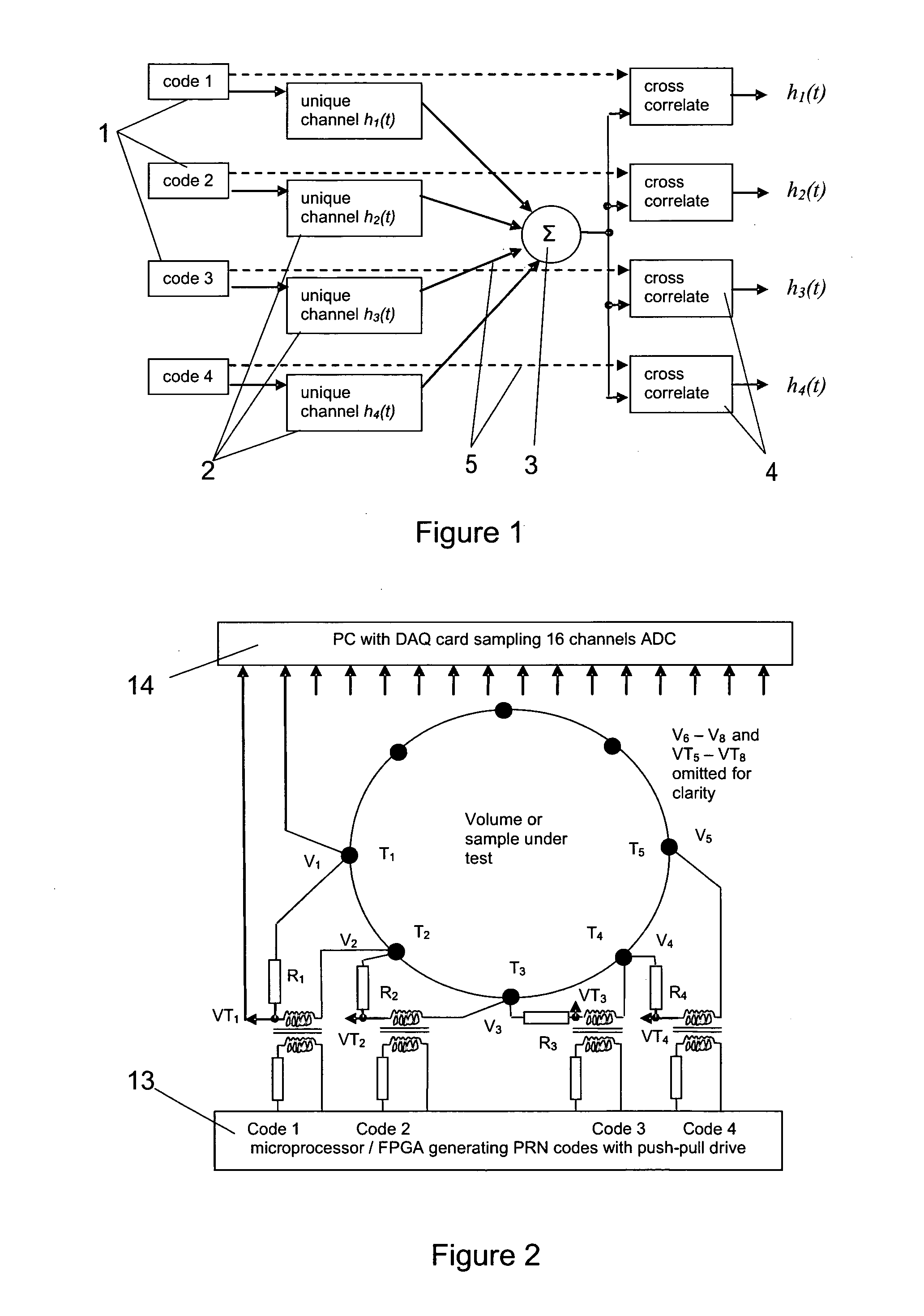
[0029]The principle of code division multiplexing (CDM) is that the signal through a particular channel is modulated using a unique binary digital code to provide, in the instance illustrated in FIG. 1, four different channels that are differently coded in the manner indicated and that are indicated by numeral (1).

[0030]The basic requirements of the codes are that there should be at least one code per channel; that the codes should be orthogonal, or nearly so; and that the autocorrelation functions of the codes should be flat with a single sharp peak (in the ideal case, approximating a delta function).

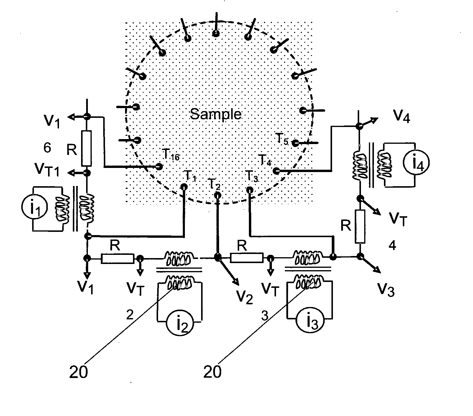
[0031]Each resulting unique channel (2) in the measurement system is thus stimulated using a driving signal current modulated with a unique code. The channels are either deliberately or inadvertently mixed together as indicated by numeral (3).

[0032]At receivers that are indicated by numeral (4), the contribution due to each channel is recovered by cross-correlating the signal at the re...


PUM


Abstract

A method is provided for taking electrical impedance tomography measurements using multiple electrodes located at selected positions external to a volume of a subject body. Multiple orthogonal or near-orthogonal signals are introduced simultaneously by way of selected different electrodes and resultant predetermined responses (if any) at receiving electrodes are recorded or determined. The signals are encoded using the technique of code division multiplexing and received signals at each receiving electrode are cross-correlated with original signals to determine the contribution of each original signal to a composite received signal. The invention also relates to apparatus suitable for use in applying a method.

Description

FIELD OF THE INVENTION[0001]This invention relates to a system and method for conducting multiplexed electrical impedance tomography for the purpose of generating images of the interior of a volume of a three-dimensional body by way of a series of electrodes applied to the outer surface thereof.[0002]More particularly, but not exclusively, the invention is concerned with a system and method for conducting multiplexed electrical impedance tomography that is particularly suitable for application in medical imaging of regions of the human body, especially for diagnostic purposes.BACKGROUND TO THE INVENTION[0003]Electrical impedance tomography (EIT), in which a volume is probed non-invasively by injecting currents (or magnetic fields) and measuring the electrical potential or magnetic fields at the periphery, has been reported as being useful for physiological imaging for some three decades.[0004]Its applicability in industrial situations, in which it is called “process tomography”, was...

Claims


Application Information

Patent Timeline
Patent Type & Authority Applications(United States)
IPC IPC(8): G06K9/00
CPCA61B5/0536G01N27/02G01V3/08
Inventor MCEWAN, ALISTAIR LEEHOLDER, DAVID SIMONVAN SCHAIK, ANDRETAPSON, JONATHAN CRAIG
Owner UNIVERSITY OF CAPE TOWN
Why Eureka
Try Eureka