
Downhole optical fiber spice housing

a technology of spice housing and downhole, applied in the field of protecting an optical fiber splice, can solve the problems of affecting the performance of downhole components,

Inactive Publication Date: 2010-12-02
BAKER HUGHES INC
View PDF15 Cites 73 Cited by
  • Summary
  • Abstract
  • Description
  • Claims
  • Application Information

AI Technical Summary

Benefits of technology

The patent describes an apparatus for protecting a splice between optical fibers in a borehole penetrating the earth. The apparatus includes a housing with two ports that seal to fiber optic cables containing the optical fibers to be spliced. The housing has a sealed interior volume sufficient to contain the splice and enable a functional bend of at least 90 degrees for at least one spliced optical fiber. The system also includes a first fiber optic cable, a second fiber optic cable, and a third fiber optic cable, which are all sealed to the housing and used to communicate the light signal between the remote location and the instruments in the borehole. The technical effect of this patent is to provide a reliable and efficient way to protect the splice between optical fibers in a borehole, which can withstand harsh environments and enable communication of light signals between the remote location and the instruments in the borehole.

Problems solved by technology

The borehole can present a very harsh environment to the downhole components.
In addition, the fluid can have abrasive and chemical properties that can damage the downhole components.
Failure of the downhole components due to the harsh borehole environment can be costly both in terms of repair and in lost production.
Unfortunately, there are a number of issues with using the upside-down Y-splice assembly.
Because the cable is armored, the minimum bend radius may be too large or cumbersome to make the bend.
Another issue is that there is a limited amount of room within the assembly such that if a splice between two bare optical fibers fails, there is limited room for excess length of unarmored optical fibers to attempt one or two more tries at splicing the optical fibers.

Method used


Image

  • Downhole optical fiber spice housing
  • Downhole optical fiber spice housing
  • Downhole optical fiber spice housing

Examples


Embodiment Construction

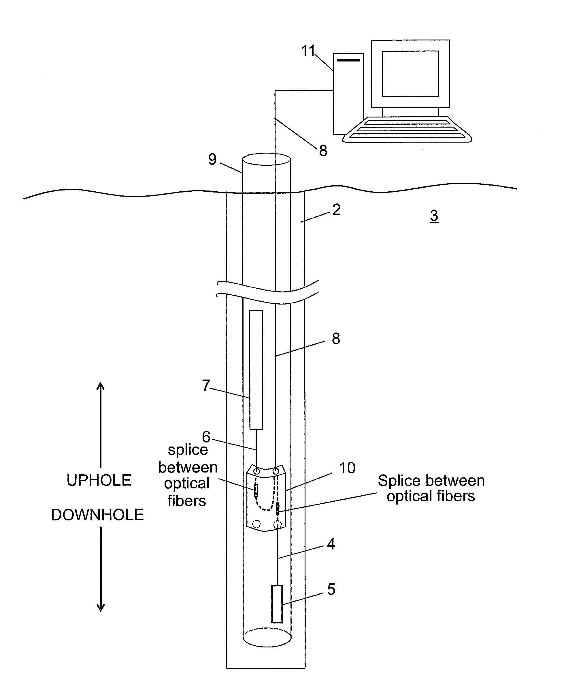
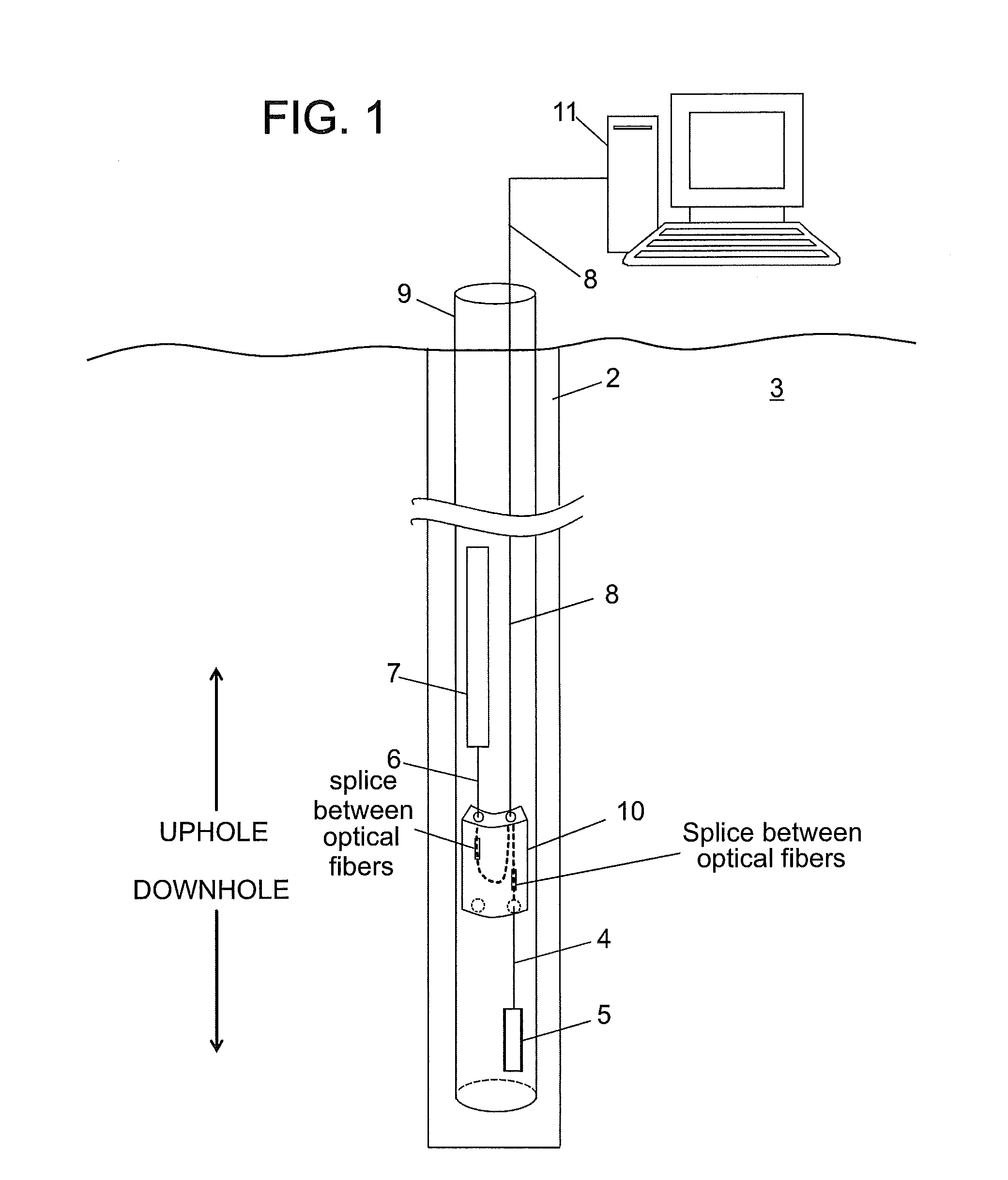
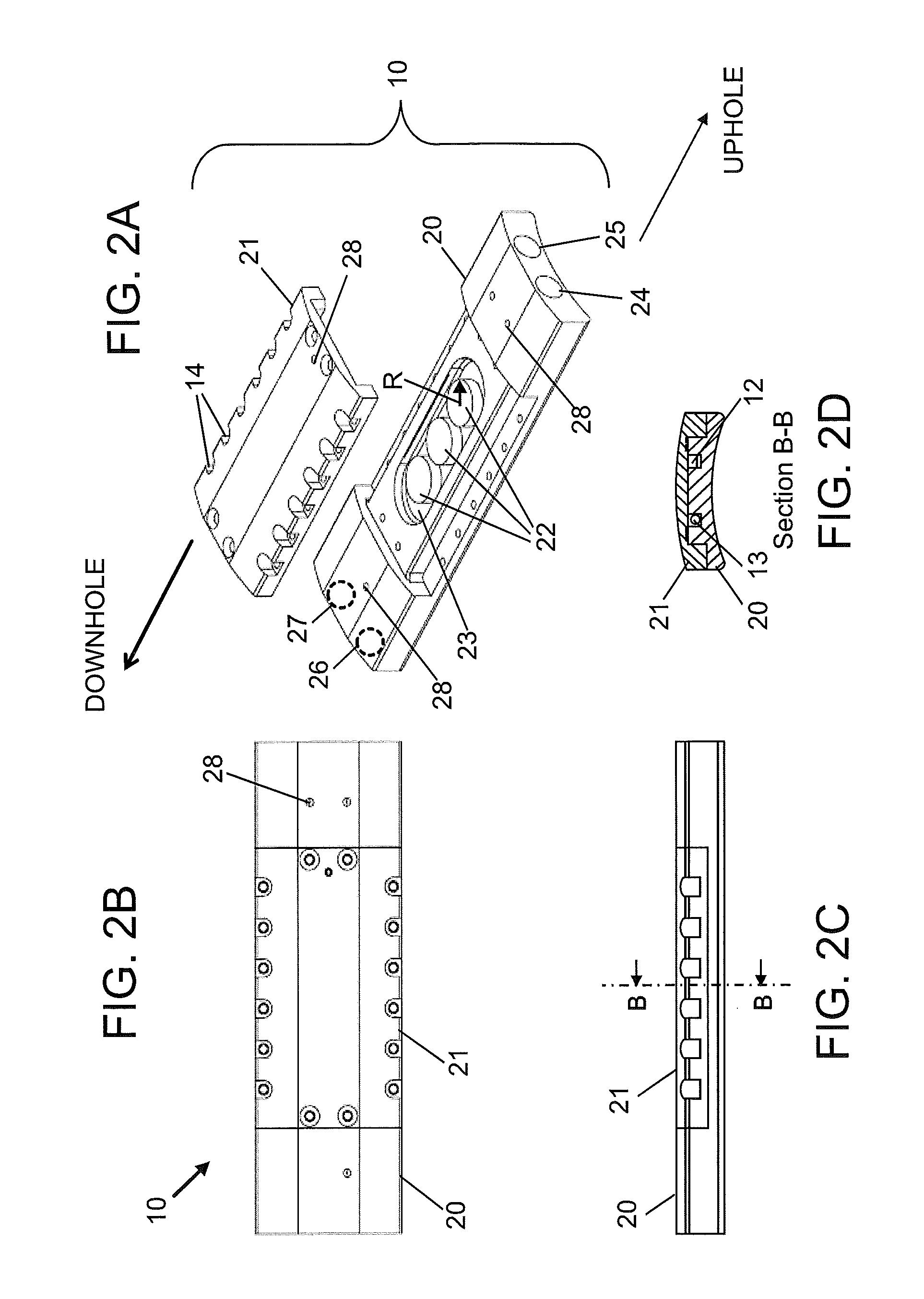
[0019]Disclosed are exemplary embodiments of techniques for protecting splices of optical fibers downhole. The techniques, which include method and apparatus, allow splices between optical fibers in fiber optic cables oriented in uphole and / or downhole directions without requiring bending an armored jacket surrounding the cable. In addition, the techniques provide for storing an excess amount of optical fibers removed from the armored jacket. The excess amount of the optical fibers allows many attempts at splicing the optical fibers before fiber optic cables containing the fibers have to be disassembled to have more of the armored jacket removed.

[0020]For convenience, certain definitions are presented. The term “downhole” relates to at least one of being located in a borehole and a direction leading to deeper or further in the borehole. A downhole direction relates to any direction having a directional component pointing downhole. The term “uphole” relates to a direction from within...


PUM


Abstract

An apparatus for protecting a splice between optical fibers disposed in a borehole penetrating the earth, the apparatus including: a housing configured to be disposed in the borehole and having a first port and a second port, each port being configured to seal the housing to an associated fiber optic cable containing an optical fiber to be spliced; wherein the housing includes a sealed interior volume sufficient to contain a splice of the optical fibers for protection and to enable a functional bend of at least ninety degrees for at least one spliced optical fiber.

Description

BACKGROUND OF THE INVENTION[0001]1. Field of the Invention[0002]The present invention relates to protecting an optical fiber splice and, in particular, to protecting the splice in a borehole environment.[0003]2. Description of the Related Art[0004]In the hydrocarbon recovery arts, a borehole is drilled into the earth for production of the hydrocarbons. Many types of components may be disposed in the borehole for the production of the hydrocarbons. Instrumentation for monitoring various conditions is one type of component that may be disposed in the borehole. In addition, a communication medium is used to communicate instrumentation measurements to the surface of the earth for processing and recording.[0005]The borehole can present a very harsh environment to the downhole components. In many cases, the borehole is filled with a fluid at a high pressure and temperature. In addition, the fluid can have abrasive and chemical properties that can damage the downhole components. Failure of...

Claims


Application Information

Patent Timeline
Patent Type & Authority Applications(United States)
IPC IPC(8): G02B6/255G02B6/00
CPCE21B47/011E21B47/123G02B6/4446E21B47/017E21B47/135G02B6/44465G02B6/44775
Inventor DAVIS, BRAD W.
Owner BAKER HUGHES INC
Learn More