Transmission chain

Inactive Publication Date: 2010-12-02
TSUBAKIMOTO CHAIN CO
View PDF12 Cites 4 Cited by
  • Summary
  • Abstract
  • Description
  • Claims
  • Application Information

AI Technical Summary

Benefits of technology

[0016]Finally, the shortening of the connecting pins makes it possible to reduce the widths of the tensioner levers and other chain guides used to restrict the path of travel of the chain.
[0017]In a preferred embodiment, the swaged end portions of each of the connecting pins have tapered inner peripheral surfaces. The cross-sectional areas of the bores of the connecting pins surrounded and defined by the tapered inner peripheral surfaces progressively decrease, proceeding from each end of the connecting pin toward the opposite end thereof. The wide openings of the tapered inner peripheral surfaces at the ends of the connecting pins improve the collection of lubricating oil so more oil can be supplied to interface between the outer peripheral surfaces of the pins and the inner peripheral surfaces of the bushings.
[0018]According to another aspect of the invention, the swaging bores in outer link plates of the outer links have tapered inner peripheral surfaces whereby the cross-sectional area of each swaging bore progressively decreases proceeding inwardly from the outside face of the outer link plate in which the swaging bore is formed. The tapering of the swaging bore prevents the connecting pins from being pulled out of the swaging bores so that strong and secure connection of the pins to the outer plates is maint

Problems solved by technology

Another problem with the conventional roller chain is that. because the connecting pins protrude beyond the sides of the outer plates 550, air resistance generates noise.
Another problem with the conventional roller chain is that, as shown in FIG. 13, the gap between the outer surface of the con

Method used


Image

  • Transmission chain
  • Transmission chain
  • Transmission chain

Examples


Example

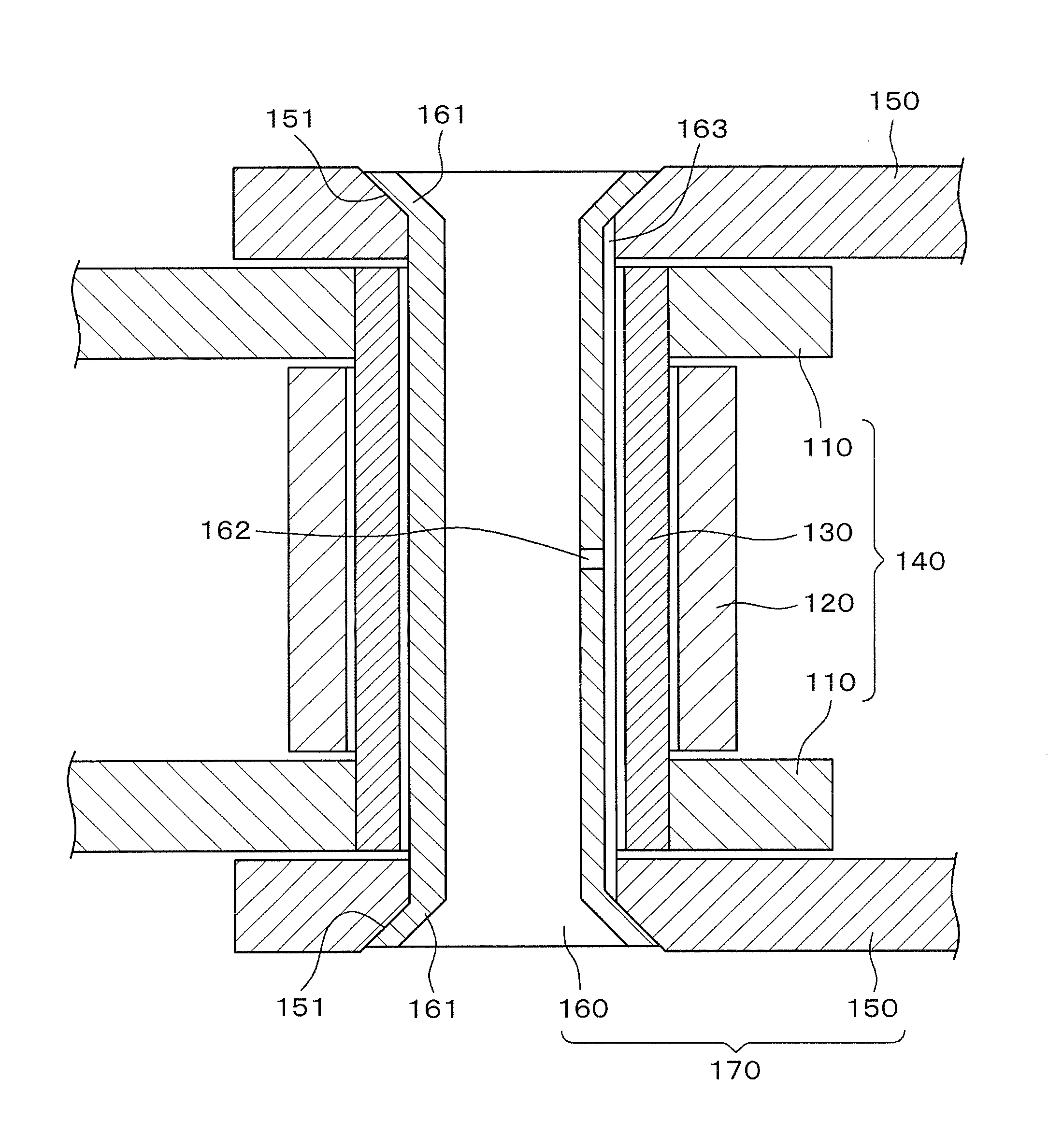
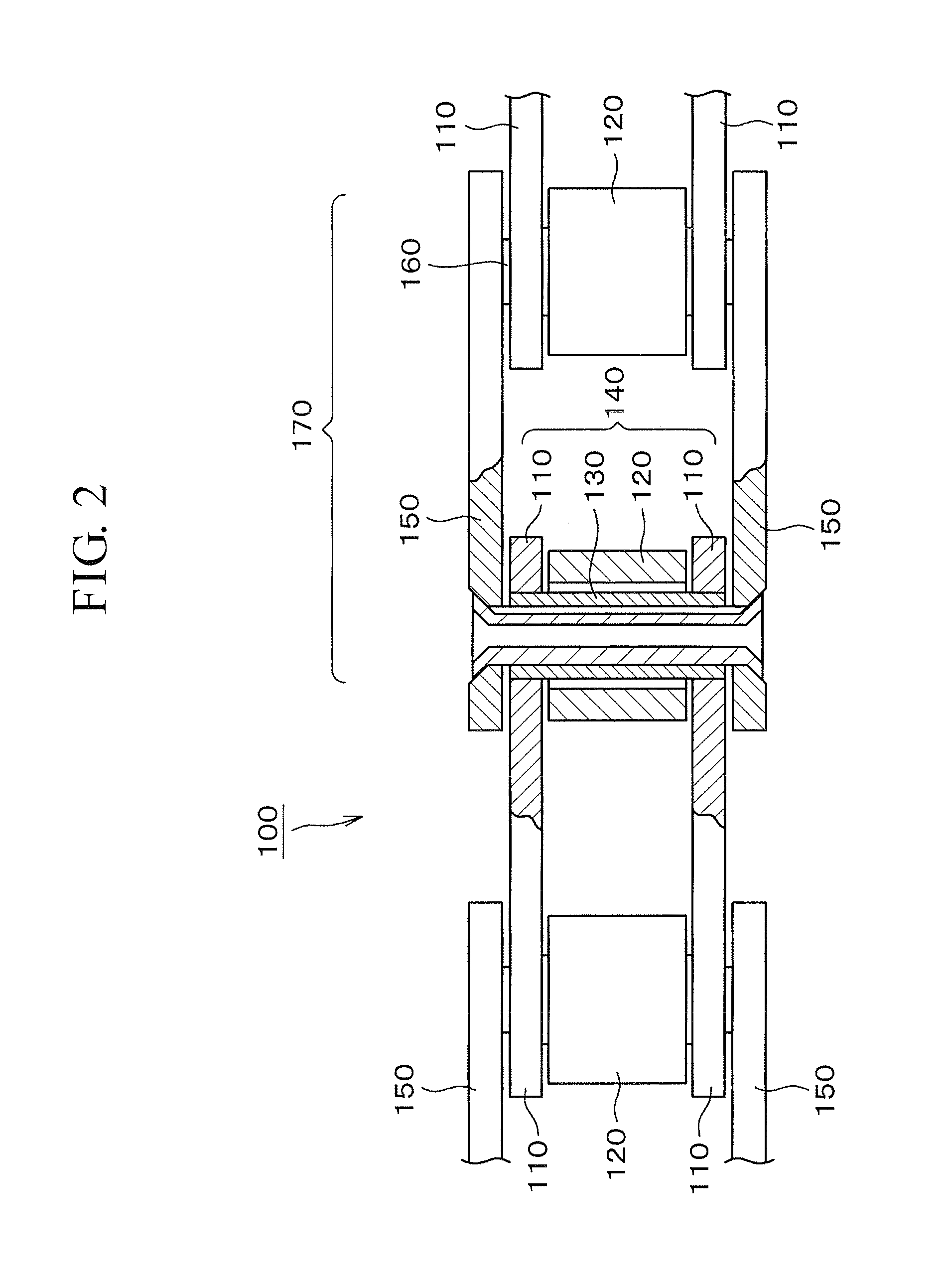
[0035]The invention can be embodied in any of a large number of variations, provided that the transmission chain has inner links with bushings, and outer links with hollow pins having swaged ends fitting in counter-bored pin holes formed in the outside faces of the outer link plates, and provided that each of the connecting pins has a bore extending therethrough along the direction of the width of the chain from an opening at one end thereof to an opening at the other end thereof, and a transverse oil communicating hole leading from the bore to the outer peripheral surface of the connecting pin.

[0036]For instance, the transmission chain of the invention can be either a roller chain or a rollerless bushing chain. The oil communicating hole may have any configuration as long as it can deliver oil from the inside of the pin to the outer peripheral surface thereof. Thus, the hole may be a circular hole and positioned at a central location along the length of the pin. Alternatively, plur...


PUM


Abstract

In a roller chain or rollerless bushing chain for transmission of power, hollow connecting pins are swaged to the plates of the outer links. Each pin has at least one oil conducting passage extending from its hollow interior to its exterior whereby lubricating oil can flow through the pin from the ends thereof and into the clearance between the pin and its surrounding bushing.

Description

CROSS REFERENCE TO RELATED APPLICATIONS[0001]This application claims priority under Title 35, United States Code, §119 (a)-(d) on the basis of Japanese Patent Application No. 2009-126093, filed on May 26, 2009. The disclosure of Japanese Patent Application No. 2009-126093 is herein incorporated by reference in its entirety.FIELD OF THE INVENTION[0002]This invention relates to a transmission chain for use in power transmission mechanisms such as the timing drive of an internal combustion engine or a transmission in an industrial machine. The invention relates more specifically to a transmission chain adapted for use in an oily environment.BACKGROUND OF THE INVENTION[0003]Automobiles and many industrial machines include power transmissions in which a transmission chain is used to transmit rotation from a driving sprocket to one or more driven sprockets. For instance, the internal combustion engine of an automobile is typically provided with a timing drive for transmitting power from a...

Claims


Application Information

Patent Timeline
IPC IPC(8): F16H57/05
CPCF16G13/06F16H57/05
Inventor OHSAWA, SEIGOKAGA, ARIMASA
Owner TSUBAKIMOTO CHAIN CO
Why Eureka
Try Eureka