Limited slip differential with positive lube flow to clutch plates

a technology of lubrication flow and clutch plate, which is applied in the direction of transportation and packaging, gearing details, and lubrication is frequently complex, and can solve the problems of limiting the amount of lubrication that can be transmitted to the first and second clutch plates, and the amount of lubrication that is received by the clutch plates can be less than desired

Inactive Publication Date: 2010-12-02
AMERICAN AXLE & MFG
View PDF17 Cites 25 Cited by
  • Summary
  • Abstract
  • Description
  • Claims
  • Application Information

AI Technical Summary

Problems solved by technology

We have noted, however, that the path for this lubrication is frequently complex and that in some situations, the complexity of this path may limit the amount of lubrication that can be transmitted to the first and second clutch plates.
Another drawback with the known lubrication systems for the clutch packs in a clutch-type limited slip differential concerns the effectiveness with which the first and second clutch plates can be lubricated.
In situations where the differential is operated at a mod

Method used


Image

  • Limited slip differential with positive lube flow to clutch plates
  • Limited slip differential with positive lube flow to clutch plates
  • Limited slip differential with positive lube flow to clutch plates

Examples


Embodiment Construction

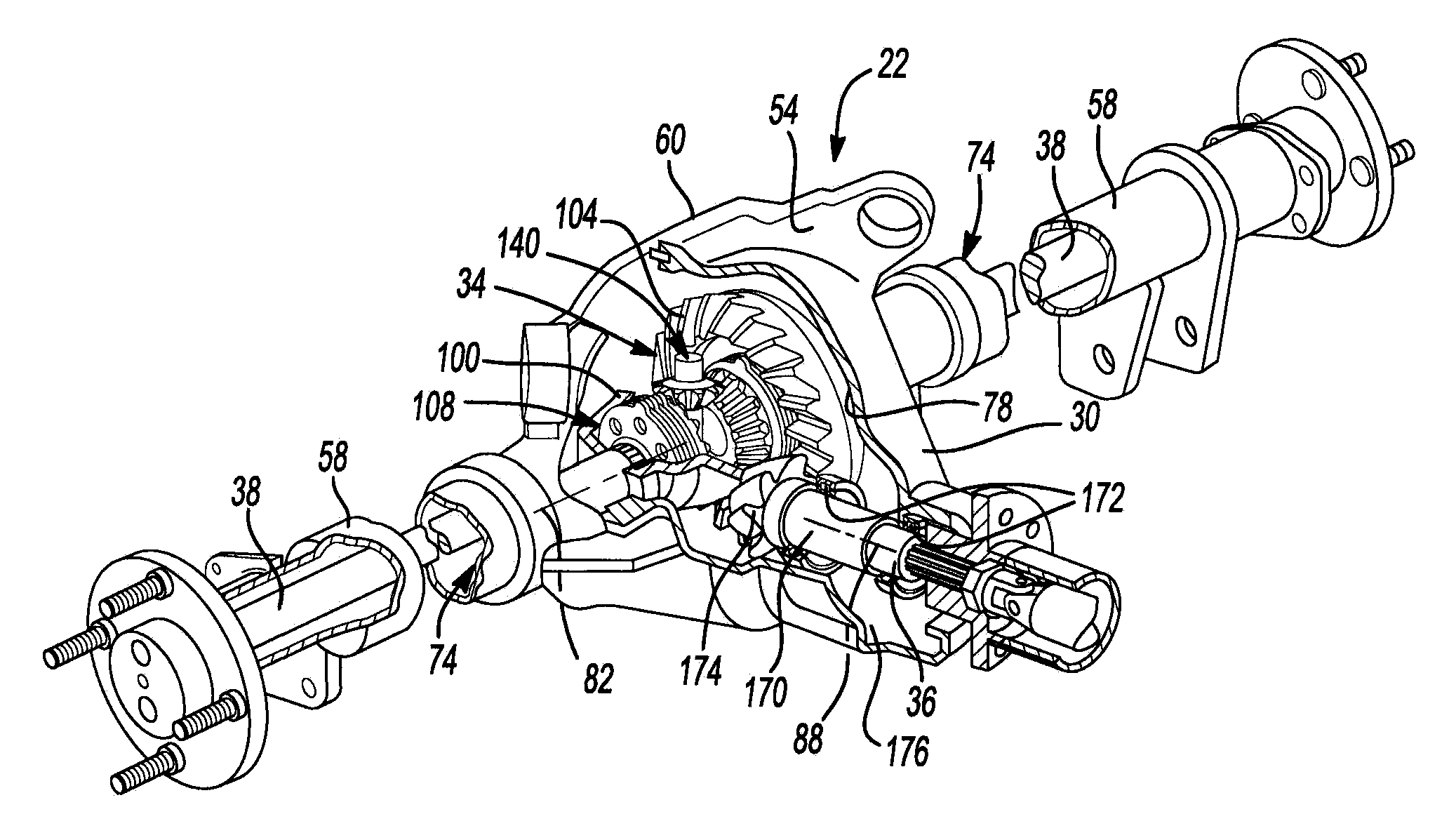
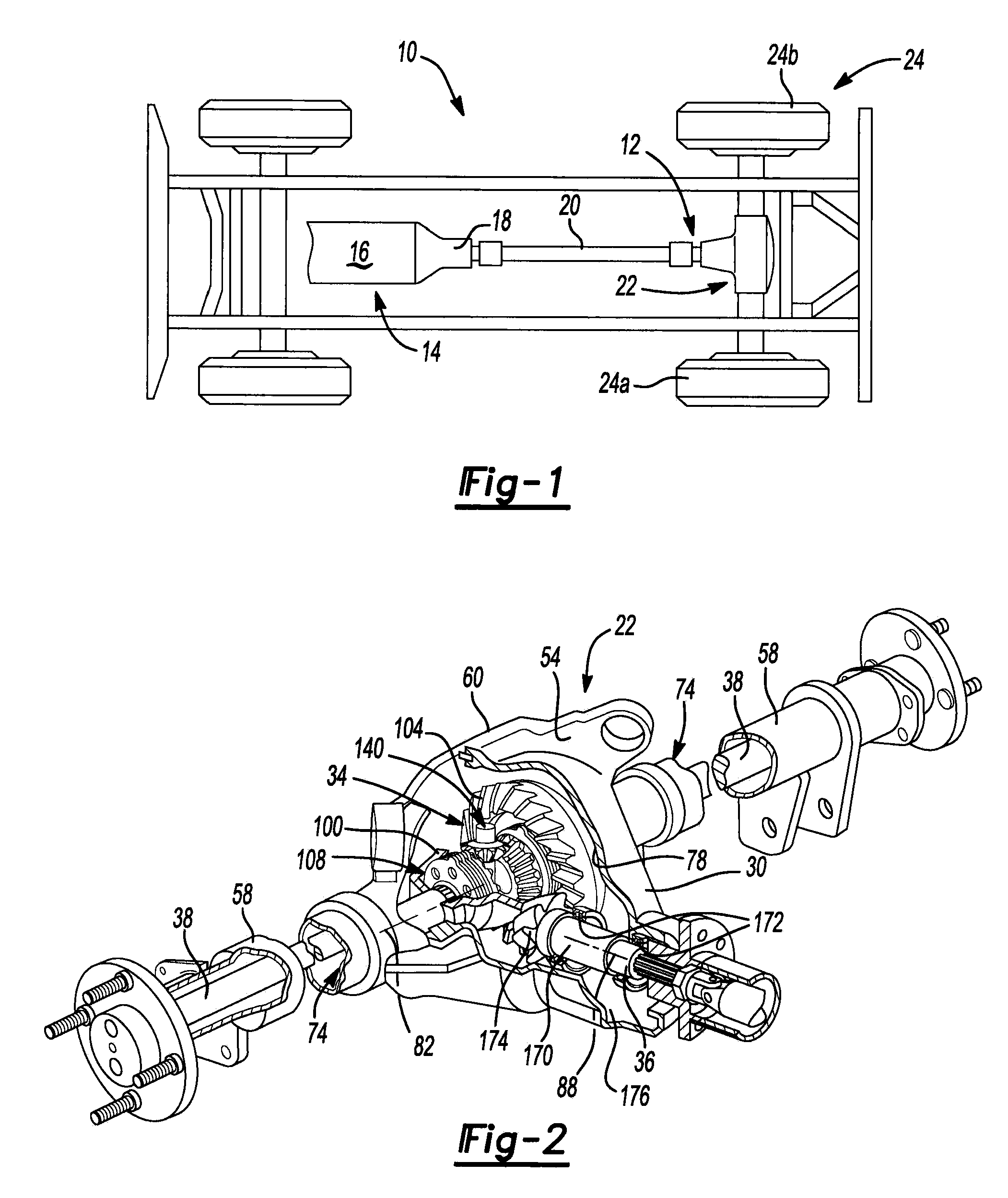
[0018]With reference to FIG. 1 of the drawings, a vehicle having a differential assembly that is constructed in accordance with the teachings of the present disclosure is generally indicated by reference numeral 10. The vehicle 10 can include a driveline 12 that is drivable via a connection to a power train 14. The power train 14 can include an engine 16 and a transmission 18. The driveline 12 can include a propshaft 20, a rear axle assembly 22 and a plurality of wheels 24. The engine 16 can be mounted in an in-line or longitudinal orientation along the axis of the vehicle 10 and its output can be selectively coupled via a conventional clutch to the input of the transmission 18 to transmit rotary power (i.e., drive torque) therebetween. The input of the transmission 18 can be commonly aligned with the output of the engine 16 for rotation about a common rotary axis. The transmission 18 can also include an output and a gear reduction unit. The gear reduction unit can be operable for c...


PUM


Abstract

A differential with a differential case, a differential gear set and a clutch pack. Apertures are formed axially through the differential case and the clutch pack to facilitate the introduction of lubricant through the differential case and into the clutch pack. An axle assembly and a method of operating an axle assembly are also provided.

Description

INTRODUCTION[0001]The present invention generally relates to a differential with improved lubrication flow to a set of clutch plates.[0002]Cutch-type limited slip differentials typically have two clutch packs each of which being mounted between the differential case and an associated side gear. Each clutch pack can include a set of first clutch plates, which can be non-rotatably coupled to the differential case, and a set of second clutch plates that can be non-rotatably coupled to an associated side gear and interleaved with the first clutch plates. The first and second clutch plates can be engaged to and released from one another depending on the amount of torque that is transmitted through the differential. With increasing torque transmission, meshing engagement of the side gears with the pinion gears of the differential can urge the side gears axially apart from one another so as to compress the clutch packs so that the first and second clutch plates frictionally engage one anot...

Claims


Application Information

Patent Timeline
IPC IPC(8): F16H57/04F16H48/22
CPCF16H48/08F16H48/22F16H57/0473F16H57/0483F16H2048/423F16H57/04B60K17/06
Inventor BARRETT, MARK S.HILKER, GREGORY J.HUNT, WILLIAM G.WOODSIDE, GREGORY E.
Owner AMERICAN AXLE & MFG
Why Eureka
Try Eureka