

Objective lens for endoscope and endoscope
a technology of objective lenses and endoscopes, applied in the field of objective lenses for endoscopes and endoscopes, can solve the problems of not desirable that too large negative distortion is generated practically, the objective lenses of endoscopes need to have sufficient long back focus, and the risk of overlooking a lesion in the peripheral area increases. , to achieve the effect of improving the image of the peripheral area and long back focus
- Summary
- Abstract
- Description
- Claims
- Application Information
AI Technical Summary
Benefits of technology
Problems solved by technology
Method used
Image

Examples
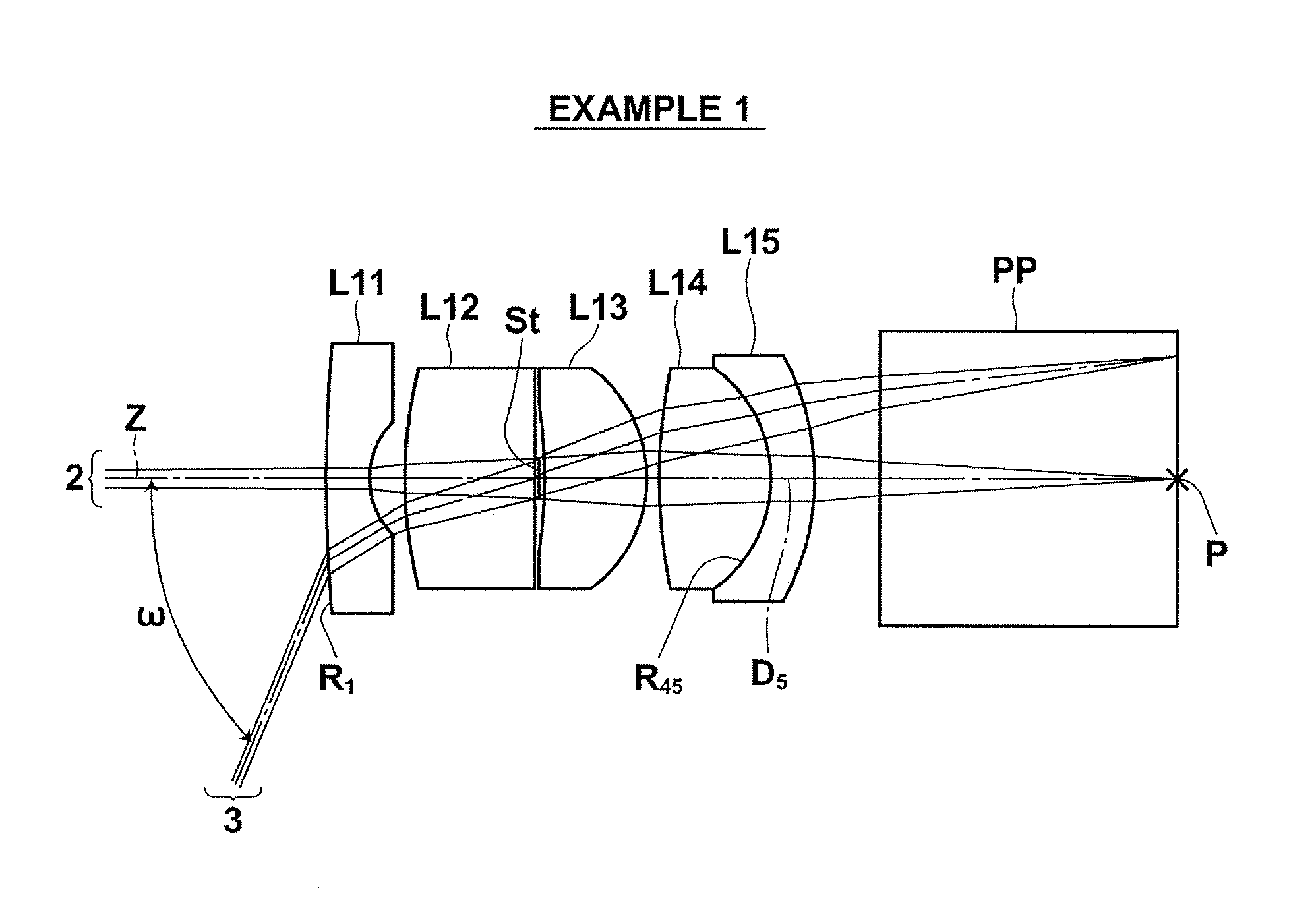
first embodiment
[0141]Further, it is desirable that the structure satisfies the following condition formula (3):
Bf / f>2.0 (3),
[0142]where Bf represents the back focus (air converted length) of the entire system of the objective lens, and f represents the focal length of the entire system of the objective lens.
[0143]When the objective lens satisfies the condition formula (3), it is possible to obtain long back focus relative to the focal length. Therefore, it is possible to arrange an optical path conversion prism between the objective lens for an endoscope and an image field.
[0144]Further, it is desirable that the structure according to the first embodiment satisfies the following condition formula (4):
f2×v4-v5R45×(Bf+D5 / n5)≥10,(4)
[0145]where Bf represents the back focus of the entire system of the objective lens, ν4 represents the Abbe number of the fourth lens for d-line, ν5 represents the Abbe number of the fifth lens for d-line, R45 represents the curvature radius of a cemented surface betw...
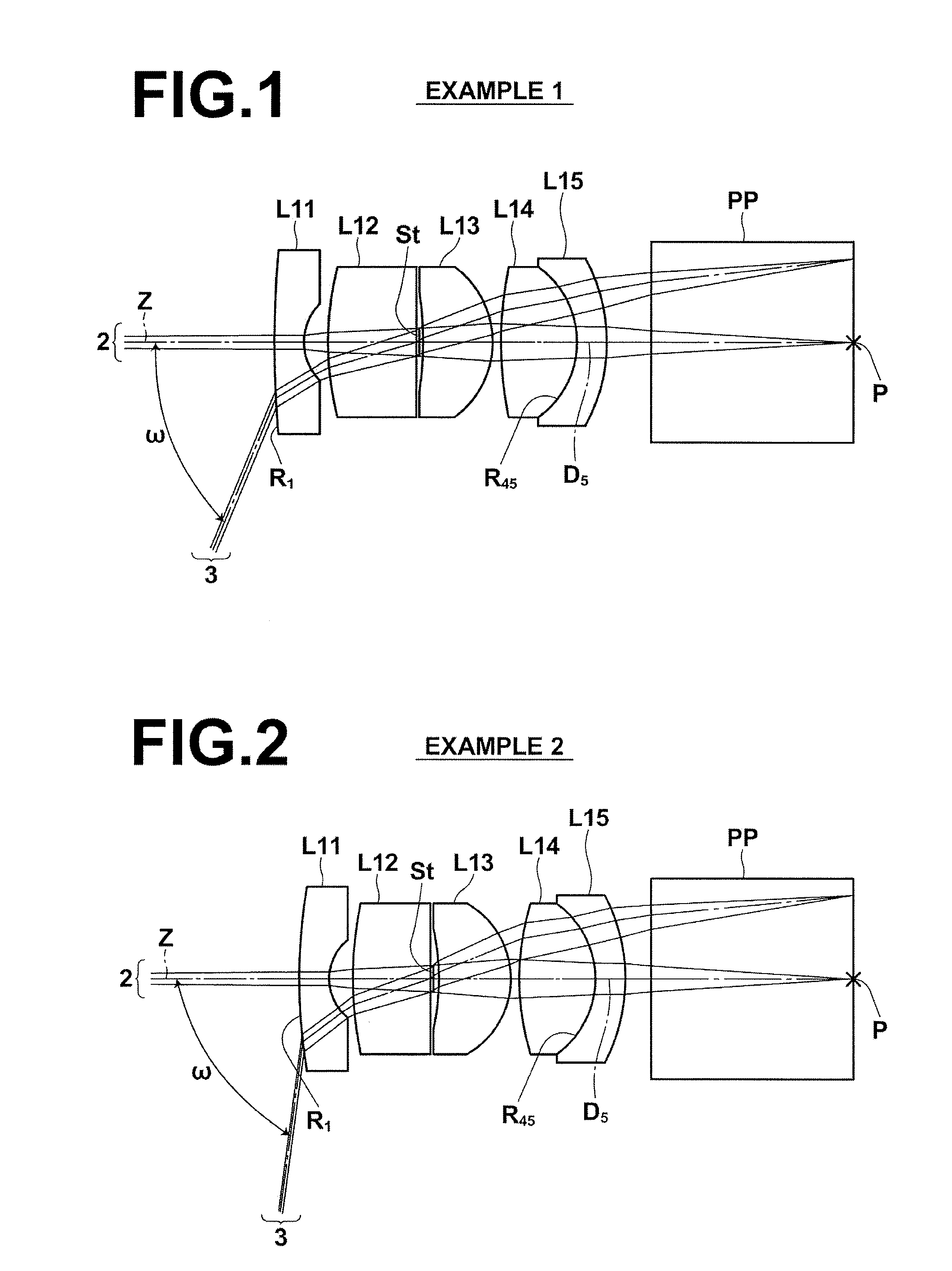
second embodiment
[0155]L22 and third lens L23 joined together, one of the second lens L22 and the third lens L23 being a positive lens and the other one of the second lens L22 and the third lens L23 being a negative lens, positive fourth lens L24 having, on the object side thereof, a flat surface or a surface the absolute value of the curvature radius of which is greater than that of the other surface thereof, and second cemented lens including fifth lens L25 and sixth lens L26 joined together, one of the fifth lens L25 and the sixth lens L26 being a positive lens and the other one of the fifth lens L25 and the sixth lens L25 being a negative lens. The negative first lens L21, the second lens L22, the third lens L23, the positive fourth lens L24, the fifth lens L25 and the sixth lens L26 are arranged in order from the object side of the objective lens. In the structure of the second embodiment, it is desirable that aperture stop St is arranged between the first cemented lens and the fourth lens L24....
PUM
 Abstract
Description
Claims
Application Information