Unfortunately, those responsible for evaluating data from monitoring devices are now overwhelmed by information from their monitoring systems.
Effectively monitoring today's electrical power distribution systems is cumbersome, expensive, and inefficient.
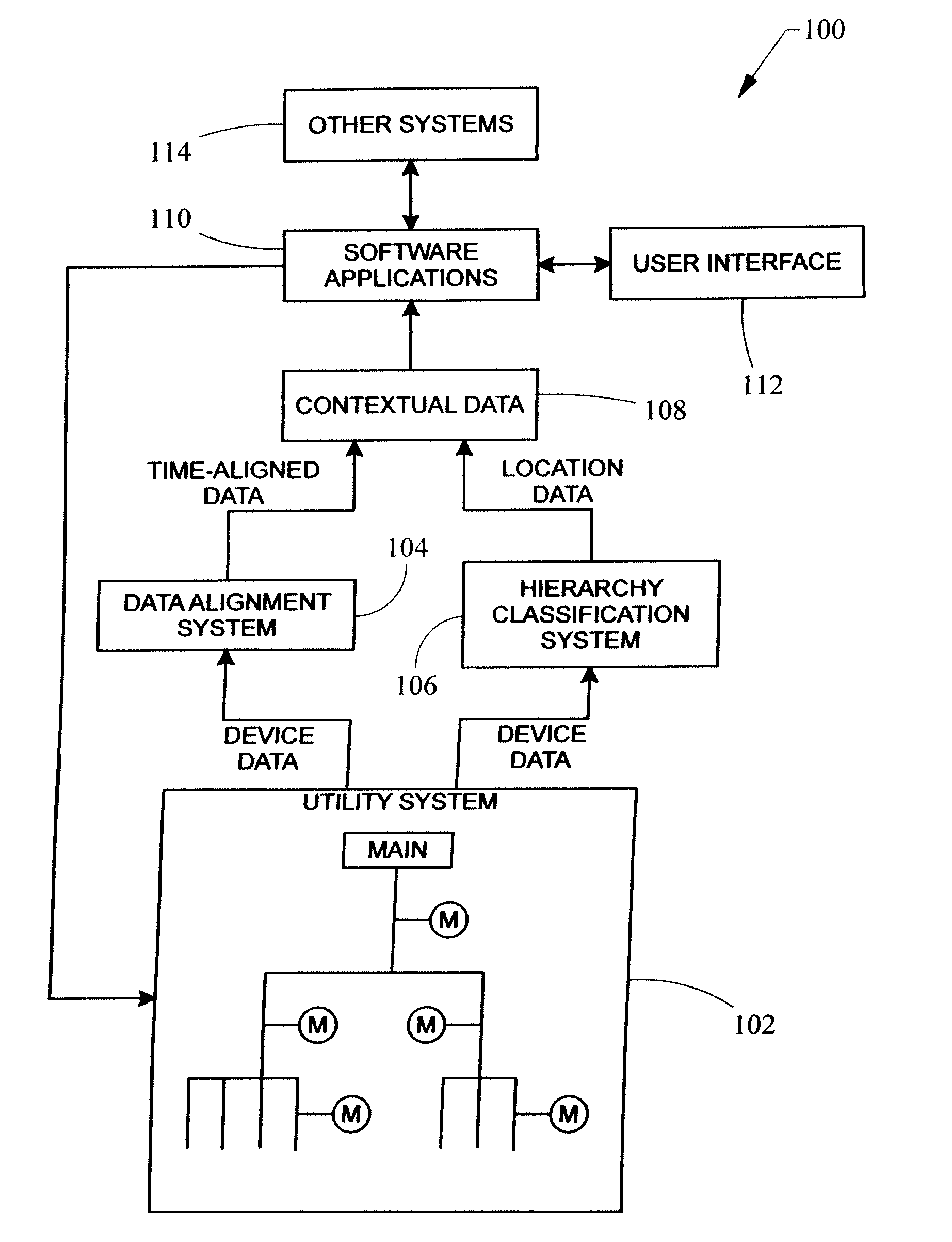
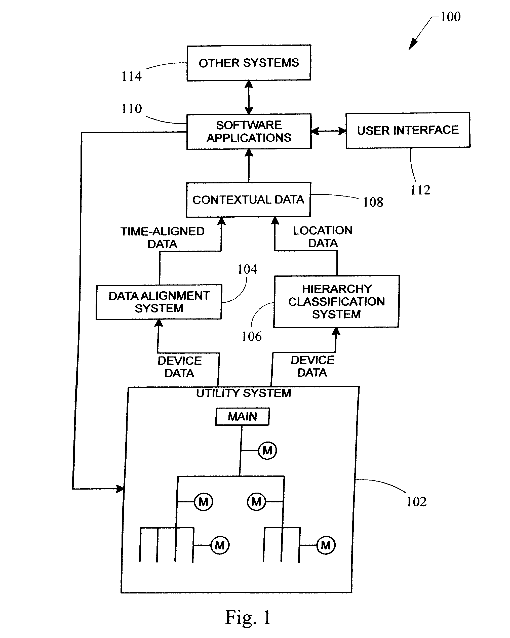
There are two problems here: the amount of data to be analyzed and the context of the data.
Accordingly, the data transmitted to the
system computer from each monitoring device is often misaligned in that data from each monitoring device on the system does not arrive at the monitoring system's computer simultaneously.
Because of the data's complexity, quantity, and relative disjointed relationship from one monitoring device to the next, manual analysis of all the data is an enormous effort that often requires experts to be hired to complete the task.
This process is tedious, complex, prone to error and oversight, and time-consuming.
And this solution still requires the evaluation of large amounts of data because the system is temporally in context; not spatially in context.
Synchronizing data using GPS systems is also disadvantageous because of
time delays associated with other hardware in the system.
Furthermore, any alignment of data by a GPS-based system can only be as accurate as the
propagation delay of the GPS
signal, which means that the data still may not be optimally aligned when a GPS system is used.
The addition of supplemental monitoring devices in the electrical system does nothing more than generate more information about the electrical system at the point where the meter is added in the electrical system, increasing complexity without any benefit.
Any usefulness of the data is generally limited to the locality of the monitoring device that was added, while even more data is amassed.
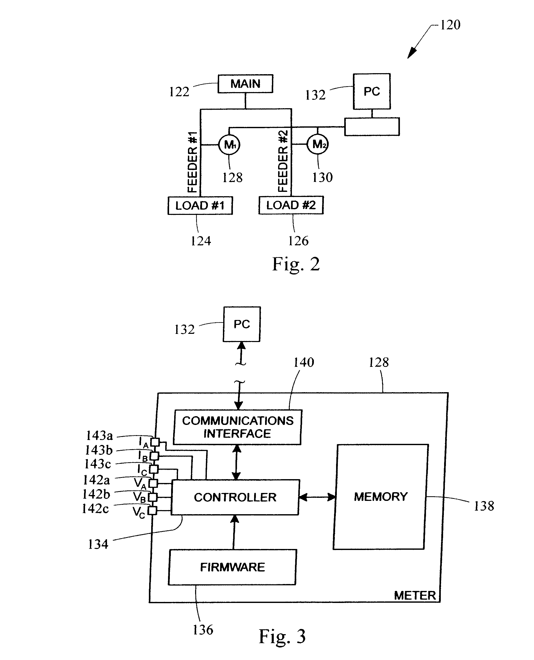
The complexity of many electrical systems usually necessitates an involved configuration process of monitoring systems because each metered point in the electrical system has different characteristics, which is why multiple monitoring devices are installed in the first place.
As a result of the enormous volume of complex data accumulated from electrical monitoring systems heretofore, a thorough analysis of the data is typically not feasible due to
limited resources, time, and / or experience.
Power monitoring devices measure the electrical system's operating parameters, but do not provide information about how the parameters at different points on the power monitoring system relate to each other.
Heretofore, the only techniques for passably integrating data were complex, expensive, manually intensive, and time-consuming for the user.
These techniques also permit only limited integration of data and require additional hardware (such as GPS hardware),
data lines, and supplemental monitoring device accessories.

