Kinetic energy accumulator and an energy transfer system incorporating a kinetic energy accumulator

a technology of kinetic energy accumulator and energy transfer system, which is applied in the direction of mechanical equipment, machines/engines, transportation and packaging, etc., can solve problems such as system inefficiency, and achieve the effect of facilitating slippag

Active Publication Date: 2010-12-09
POWER 4 COUNTRY PTY
View PDF15 Cites 12 Cited by
  • Summary
  • Abstract
  • Description
  • Claims
  • Application Information

AI Technical Summary

Benefits of technology

[0020]The permanent magnets desirably comprise rare earth magnets. The magnetic coupling facilitates slippage and, consequentially, smooth dynamic coupling between adjacent ones of the accumulator members.
[0021]A secondary magnet system can be employed for biasing the coupling members in a manner to sever magnetic coupling of adjacent accumulator members when the angular velocity of a given accumulator member falls below that of the predetermined velocity.

Problems solved by technology

However, the flywheels are all driven at the same time by the motor to accumulate kinetic energy in the system, making the system inefficient.

Method used


Image

  • Kinetic energy accumulator and an energy transfer system incorporating a kinetic energy accumulator
  • Kinetic energy accumulator and an energy transfer system incorporating a kinetic energy accumulator
  • Kinetic energy accumulator and an energy transfer system incorporating a kinetic energy accumulator

Examples


Embodiment Construction

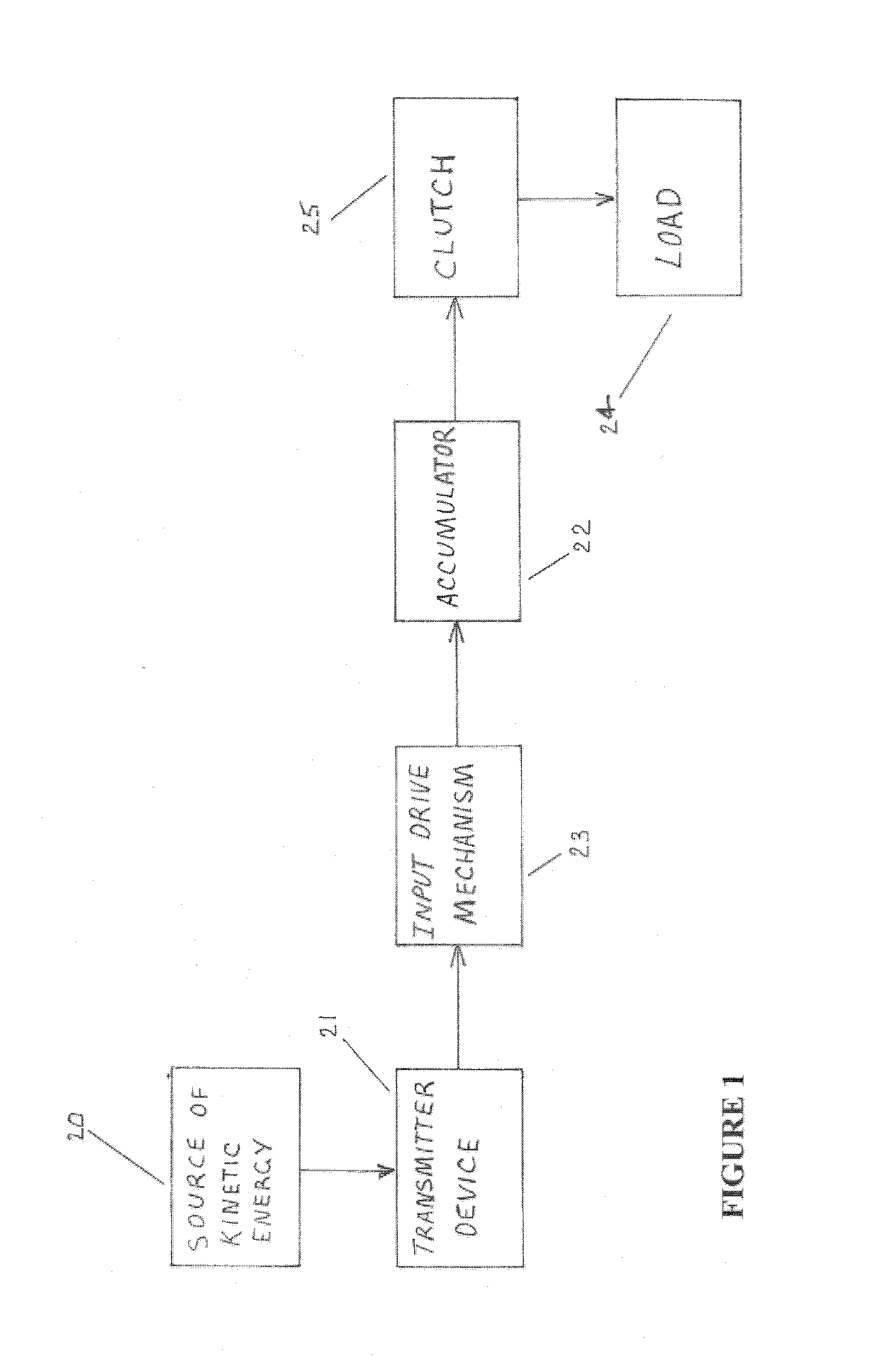
[0068]As illustrated in FIG. 1, the energy transfer system comprises a source 20 of kinetic energy which, in operation of the system, delivers kinetic energy to an energy transmitter 21. The source 20 will typically comprise a succession of moving vehicles which, in engaging with the transmitter 21, does work on, by imparting movement to, the transmitter 21. However, as indicated previously, the energy source might alternatively comprise any moving object that has the capacity to impart movement to the transmitter 21.

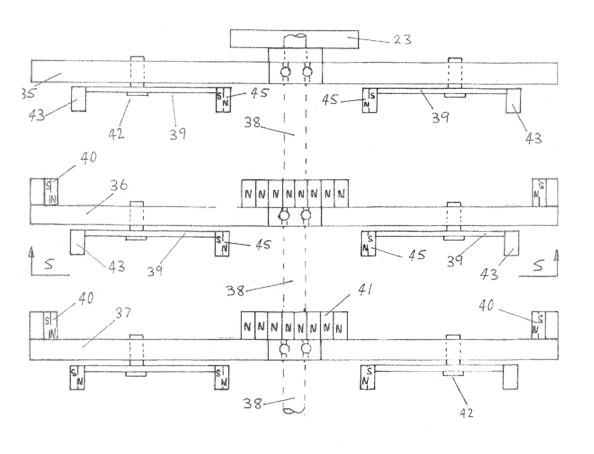
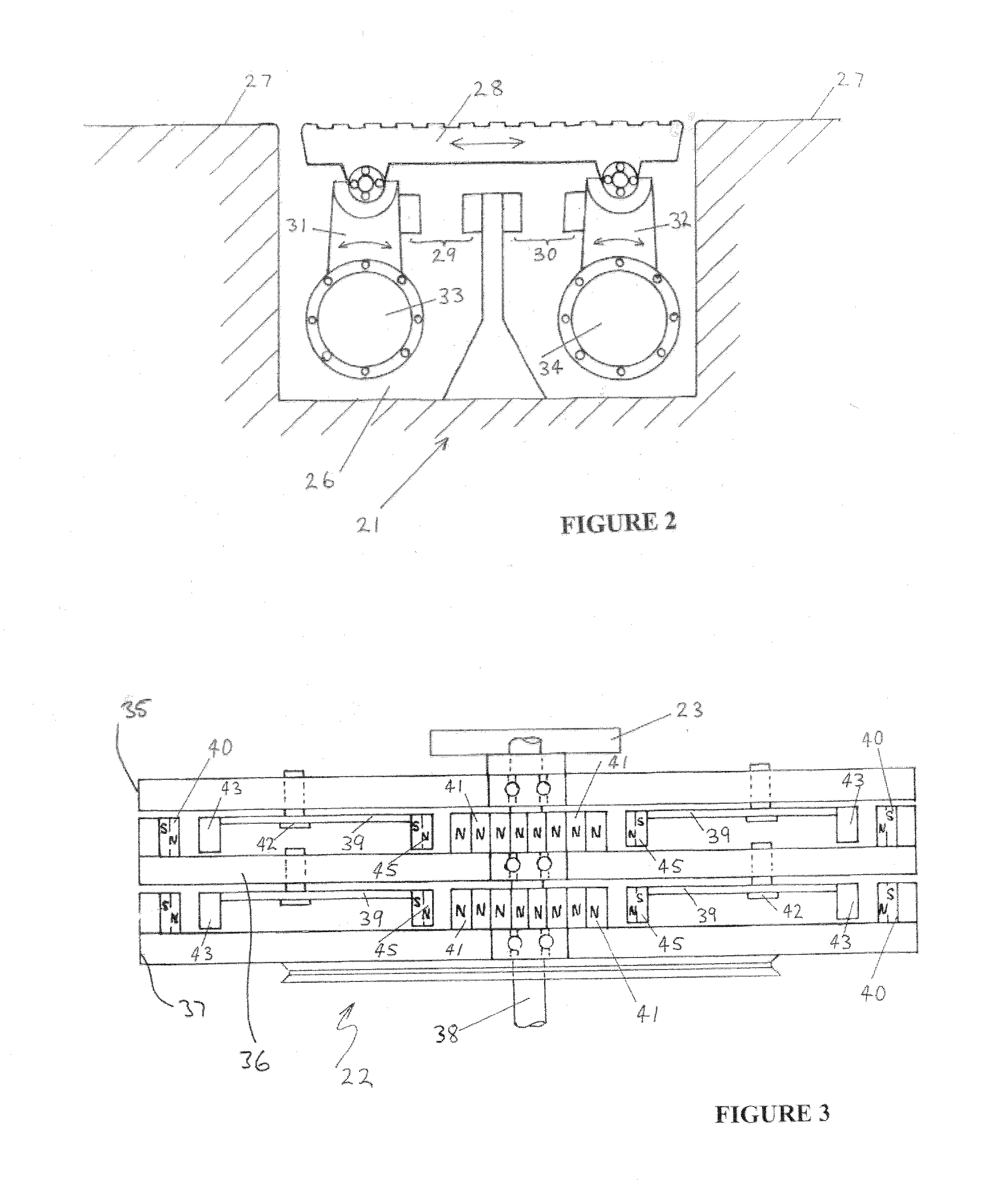
[0069]Energy input to the transmitter 21 is transmitted in the form of incremental mechanical movement to an accumulator 22 by way of an input drive mechanism 23. When sufficient kinetic energy is accumulated in the accumulator 22 to overcome the static inertia of a load 24, drive is delivered to the load from the accumulator (by way of a clutch 25, e.g., a centrifugal clutch) for such time as energy is input incrementally to the accumulator from the source 20.

[0070]The...


PUM


Abstract

The invention relates to a kinetic energy accumulator, comprising a plurality of rotatably mounted accumulator members (100, 198) positioned adjacent one another, an input drive mechanism (116) arranged to impart rotational drive to a first of the accumulator members, and velocity responsive coupling members (106, 192) arranged to provide for magnetic coupling of successive ones of the accumulator members when respective ones of the accumulator members are caused successively to rotate with an angular velocity equal to, or greater than, a predetermined velocity. The accumulator can store kinetic energy and thereby act as source of rotational drive. Hence, there is also provided a kinetic energy transfer system, comprising the kinetic energy accumulator (118), an energy transmitter mechanism arranged to apply drive from a kinetic energy source to the input drive mechanism (116) of the energy accumulator; and a load device coupled to, and arranged to be driven by, the energy accumulator when each of the accumulator members is rotating with an angular velocity equal to, or greater than, the predetermined velocity. The load device can be an electric generator or other device.

Description

FIELD OF THE INVENTION[0001]This invention relates to a kinetic energy accumulator and, in one of its embodiments, to an energy transfer system incorporating such accumulator.BACKGROUND OF THE INVENTION[0002]Various types of kinetic energy accumulators are known, including those that embody the flywheel principle, for use in systems that require the accumulation and / or smoothing of (regular or irregular) oscillatory or pulsating energy in its transfer from a source to a load. Similarly, various types of energy transfer systems, some of which incorporate accumulators, have been proposed for transferring kinetic energy from moving vehicles to electrical or fluid-pressure generators. In this context reference is made to the disclosures of U.S. Pat. No. 4,239,975 (Chiappetti) filed 30 Apr. 1979 and U.S. Pat. No. 6,767,161 (Calvo et al) filed 2 Dec. 2002.[0003]U.S. Pat. No. 5,590,568 (Takara) granted 7 Jan. 1997 describes a flywheel energy storage system for being driven by a low output ...

Claims


Application Information

Patent Timeline
Patent Type & Authority Applications(United States)
IPC IPC(8): F16F15/30H02K49/10
CPCH02K16/00Y02T10/6204H02K49/10B60K6/105H02K7/02F03G7/08H02K49/106Y02E60/16Y10T74/18368F03G3/00Y10T74/2117Y10T464/30H02K7/025Y02T10/62F03G7/081F05B2260/4023F05B2220/7068F05B2260/504F03G7/087
Inventor UNDERWOOD, PERRY JOHN
Owner POWER 4 COUNTRY PTY
Why Eureka
Try Eureka