Methods and apparatus for suspending a vehicle shield

a vehicle shield and suspension technology, applied in the direction of shock absorbers, machine supports, transportation and packaging, etc., can solve the problems of increasing the vehicle's mass, particularly the underside of the vehicle, and being particularly vulnerable to non-discriminating devices, so as to achieve the effect of attenuating the blast

Active Publication Date: 2010-12-09
FOX FACTORY
View PDF53 Cites 62 Cited by
  • Summary
  • Abstract
  • Description
  • Claims
  • Application Information

AI Technical Summary

Benefits of technology

[0010]A shock absorber system for a vehicle includes features that attenuate bla

Problems solved by technology

The underside of the vehicle is particularly vulnerable to non-discriminating devices such as land mines.
While some veh

Method used


Image

  • Methods and apparatus for suspending a vehicle shield
  • Methods and apparatus for suspending a vehicle shield
  • Methods and apparatus for suspending a vehicle shield

Examples


Embodiment Construction

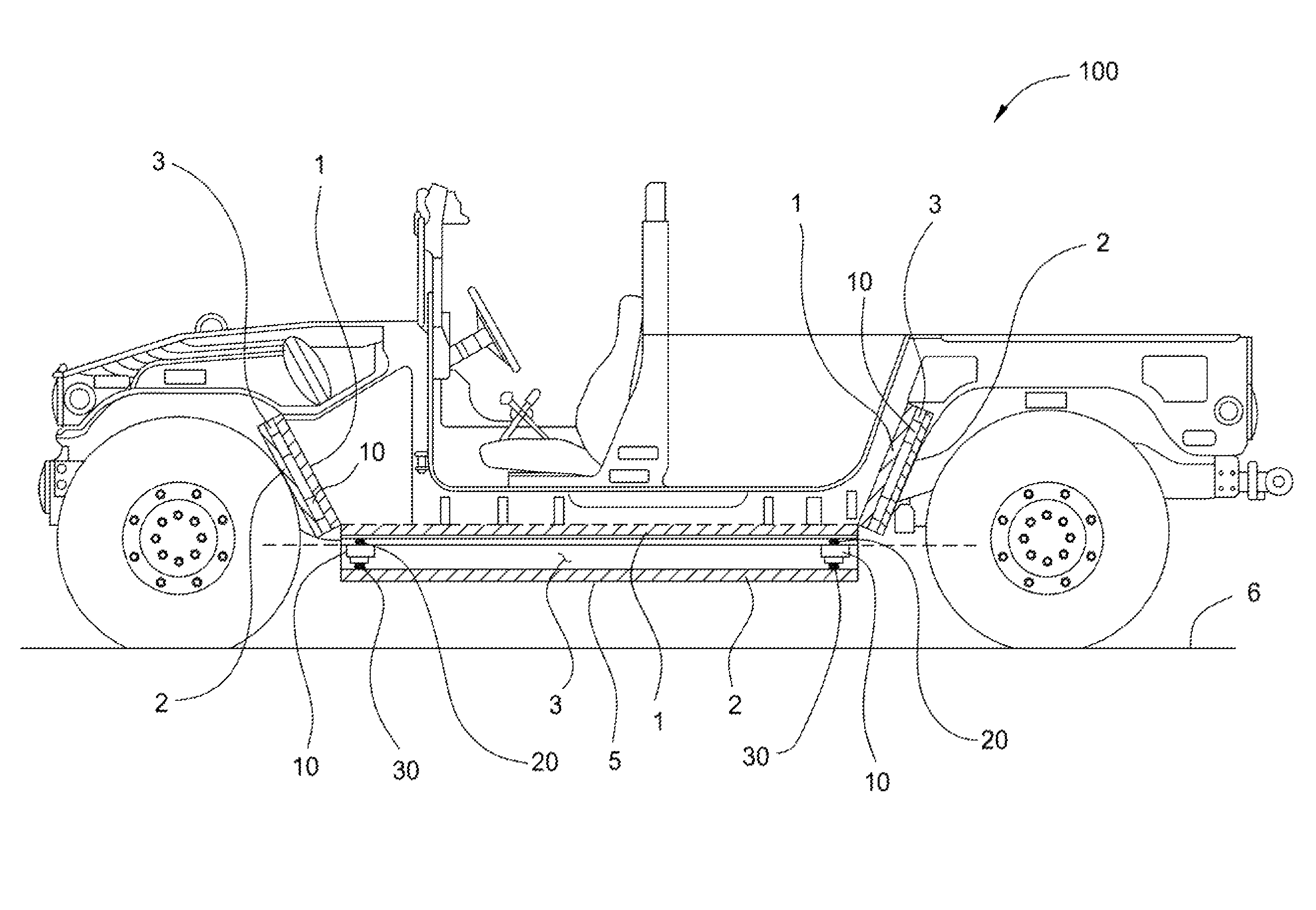
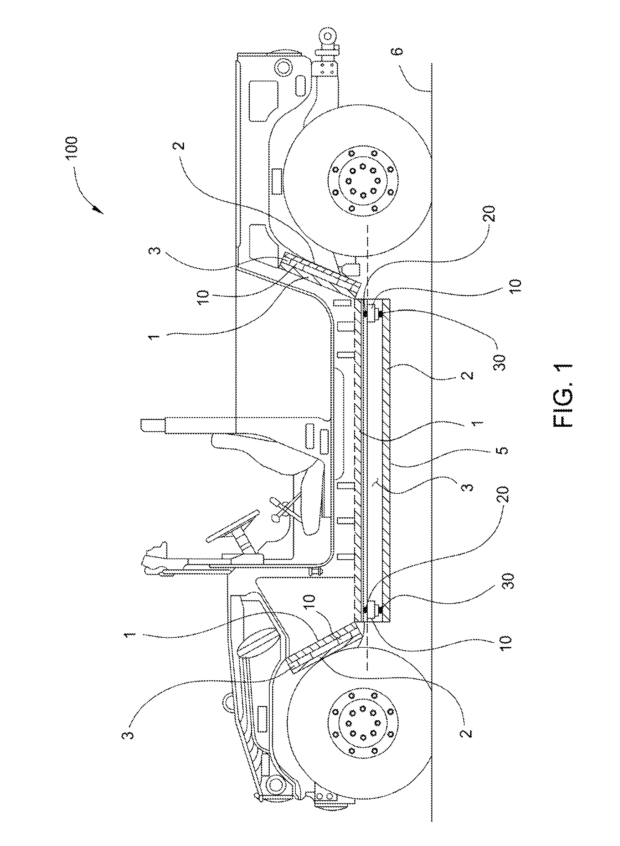
[0014]FIG. 1 shows an embodiment of the invention including three shields 2 mechanically suspended at various locations on a vehicle 100. In each case, the shield 2, which includes a shock receiving surface 3, is separated from the vehicle 100 by an air gap 3. In the embodiment shown, each shield is flanked by a shield base 1 to further define the air gap 3 and facilitate the attachment and operation of the shield 2. FIG. 1 shows shields disposed in an area under the passenger compartment and also in the areas of the wheels wells but the shields and shock absorbers disclosed herein can be installed anywhere in relation to a vehicle including engine / drive train areas, fuel tanks and anywhere else that might be subjected to a shock event.

[0015]Shock absorbers 10 are disposed in each air gap 3 between the shield 2 and shield base 1. In the embodiment of FIG. 1, the shock absorbers structurally maintain the primary shield 2 relative to shield base 1. For example, the shock absorbers 10 ...


PUM


Abstract

A shock absorber system for use with a vehicle having a shield to reduce the effects of a shock event.

Description

CROSS-REFERENCE TO RELATED APPLICATIONS[0001]This application claims benefit of U.S. provisional patent application Ser. No. 61 / 184,644, filed Jun. 5, 2009, which is herein incorporated by reference.BACKGROUND OF THE INVENTION[0002]1. Field of the Invention[0003]Embodiments of the present invention generally relate to a shock absorber system for use with a vehicle having a shield to reduce the effects of a shock event.[0004]2. Description of the Related Art[0005]Integrated damper / spring vehicle shock absorbers often include a damper body surrounded by a mechanical spring. The damper often consists of a piston and shaft telescopically mounted in a fluid filled cylinder. The mechanical spring may be a helically wound spring that surrounds the damper body. Various integrated shock absorber configurations are described in U.S. Pat. Nos. 5,044,614, 5,803,443, 5,553,836 and 7,293,764, each of which is herein incorporated in its entirety by reference.[0006]Some shock absorbers utilize gas ...

Claims


Application Information

Patent Timeline
IPC IPC(8): F41H7/02F16F7/00F16F9/02F16F9/06F16F9/34F16F9/30F16F9/44
CPCF16F9/06F16F9/10F41H7/042F41H5/013F41H5/023F16F9/3207
Inventor KASWEN, ROBERTHAUGEN, DAVID M.
Owner FOX FACTORY
Why Eureka
Try Eureka