Ultra-high velocity projectile impact sensor

a projectile impact sensor and ultra-high-speed technology, applied in the field of sensors, can solve the problems of insufficient method, inability to send impact notification messages, and limited sound through metal construction materials of projectiles to limit the propagation speed of shock waves

Inactive Publication Date: 2010-12-09
RAFAEL ADVANCED DEFENSE SYSTEMS
View PDF12 Cites 13 Cited by
  • Summary
  • Abstract
  • Description
  • Claims
  • Application Information

AI Technical Summary

Problems solved by technology

The speed of sound through the metal construction materials of a projectile limits the propagation speed of the shock wave from an impact through the projectile.
If the electrical sensor is positioned at the anticipated area of impact, the sensor will be destroyed on impact, hence unable to send an impact notification message.
This method is not sufficient at ultra-high velocities because the velocity of the destructive shock wave through the projectile structure exceeds the speed of the sound in the materials of which the projectile is constructed, so the sensor is destroyed before being able to detect the impact.
When the projectile impacts, the conductive circuit is destroyed before the sensor is destroyed.
At these velocities, the impact results in damage to the conductive circuit, for example breaking of the conductivity of the circuit.
This technique of using a conductive circuit is not sufficient to detect ultra-high velocity projectile impacts because of the type of destruction resulting from the impact.
The unpredictable effects of an ultra-high velocity impact on electrical circuitry may be because of the possible formation of plasma, or other unpredictable physical phenomena, due to the velocity of the impact exceeding the speed of sound in the material.
The operation of a conductive circuit under these conditions cannot be predicted reliably.
The destruction of a conductive circuit at ultra-high velocities does not provide a reliable change in the signal.
For example, the conductive circuit may short instead of breaking, or may have a non-repeatable response.

Method used


Image

  • Ultra-high velocity projectile impact sensor
  • Ultra-high velocity projectile impact sensor
  • Ultra-high velocity projectile impact sensor

Examples


Embodiment Construction

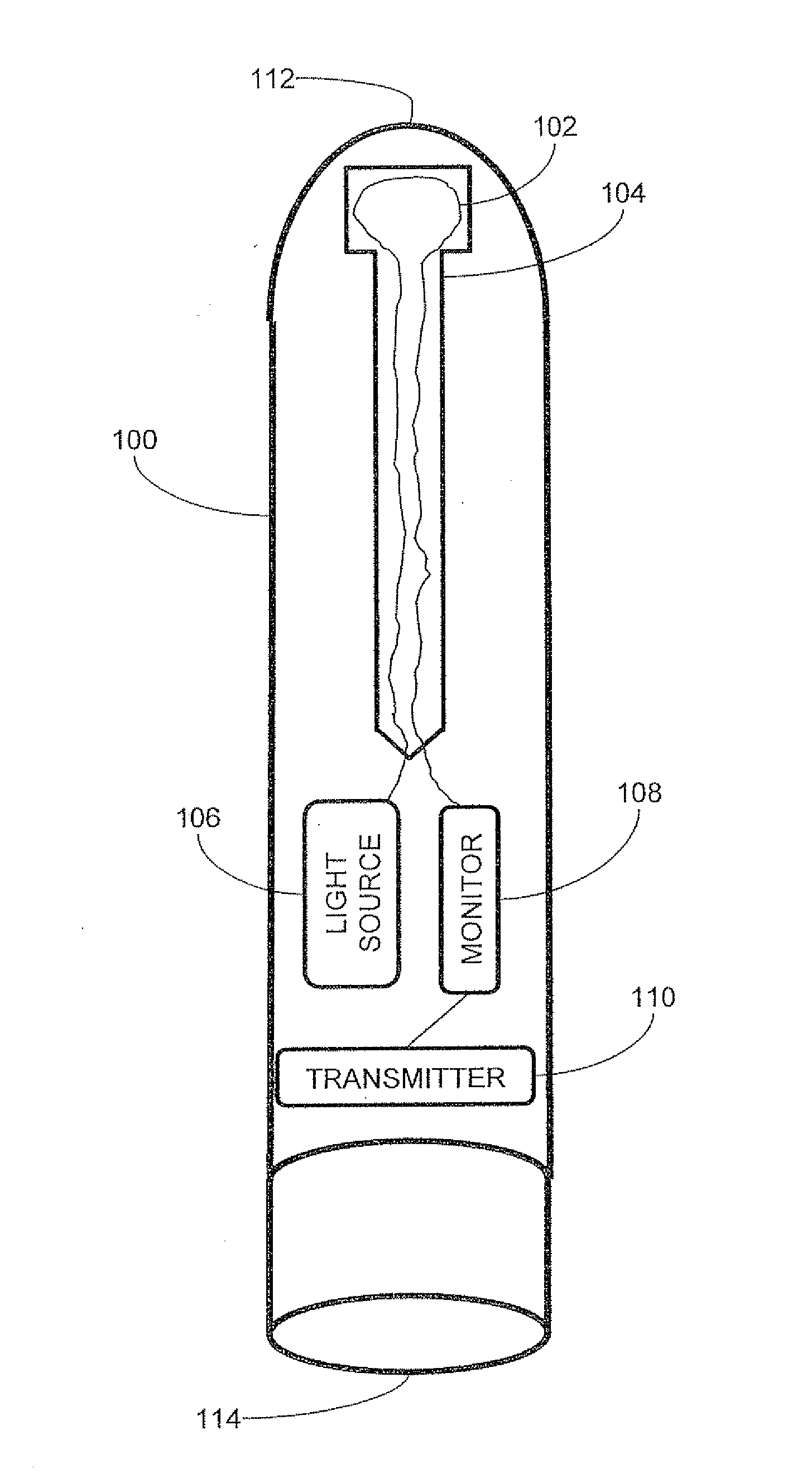
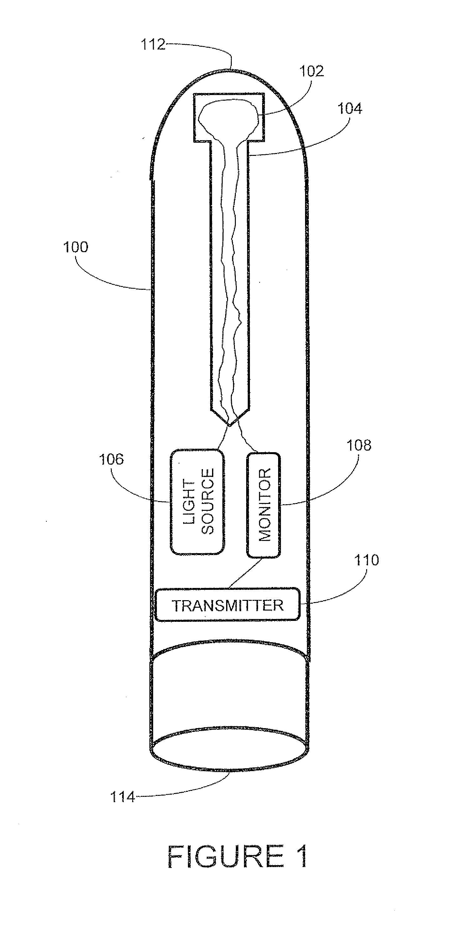
[0016]The present invention is an apparatus and method for detecting the impact of an ultra-high velocity projectile impact. The principles and operation of this apparatus and method according to the present implementation may be better understood with reference to the drawings and the accompanying description.

[0017]Referring now to the drawings, FIG. 1 is a diagram of a projectile 100 that can travel at ultra-high velocities. In the context of this invention, the term ultra-high velocity refers to collisions occurring at relative velocities above about 1500 m / s. When the projectile collides with a target, the impact results in the destruction of the projectile. When a projectile strikes a target, it is desirable to know that the impact occurred. In this case, the projectile needs to send a notification that it has had an impact after the impact has occurred, but before the projectile is destroyed by the impact. As described in the background section of this document, conventional s...


PUM

PropertyMeasurementUnit
relative velocitiesaaaaaaaaaa
velocitiesaaaaaaaaaa
relative velocitiesaaaaaaaaaa

Abstract

An apparatus for detecting the impact of an ultra-high velocity projectile includes: a projectile; at least one optical fiber attached to at least a first area of the projectile; a light source coupled to the optical fiber supplying light into the optical fiber; and a monitor coupled to optical fiber configured to monitor the light in one optical fiber and positioned in a second area of the projectile. A method for operating a circuit in response to a shockwave of ultra-high velocity, includes the steps of deploying at least one optical fiber in a first area in the path of an ultra-high velocity shockwave; coupling a light source to the optical fiber, the light source supplying a light into the optical fiber; and deploying a monitor coupled to the optical fiber to: monitor the light in the optical fiber to detect a change in the light; and positioned in a second area further along the path of the shockwave.

Description

[0001]This patent application claims priority of Israel Patent Application No. 199142 filed Jun. 3, 2009, which is incorporated herein by reference in its entirety.FIELD OF THE INVENTION[0002]The present invention generally relates to the field of sensors, and in particular to the area of an ultra-high velocity projectile self-sensing an impact with another object.BACKGROUND OF THE INVENTION[0003]Shock and impact sensors are devices that detect sudden movements, changes, or severe impacts at a predetermined level and indicate whether that level has been exceeded. Impact sensors are used in applications where it is desirable to know when an impact has occurred. In an ultra-high velocity impact, the relative velocities of the colliding objects can be about 5000 meters per second (m / s) or higher which is about the speed of sound in metal. The speed of sound through the metal construction materials of a projectile limits the propagation speed of the shock wave from an impact through the...

Claims


Application Information

Patent Timeline
Patent Type & Authority Applications(United States)
IPC IPC(8): F42C19/07G01N3/30
CPCF42C19/07F42C1/10G01P15/06G01P15/0891
Inventor CHISHINSKI, EHUD
Owner RAFAEL ADVANCED DEFENSE SYSTEMS
Why Eureka
Try Eureka