Folding land rolling implement

a technology of rolling implements and rolling implements, applied in the direction of harrows, ploughs, spades, etc., can solve the problem of problematic placement of sections in transport positions

Active Publication Date: 2010-12-09
RITE WAY MFG
View PDF27 Cites 15 Cited by
  • Summary
  • Abstract
  • Description
  • Claims
  • Application Information

AI Technical Summary

Benefits of technology

[0009]Thus the present invention provides an implement for rolling or packing a field surface that can be very wide while providing a compact transport width with the wings aligned behind the center section such that a width of the apparatus when in the transport position is substantially equal to a width of the center section. Where the implement is a land roller, the rollers are typically about 42 inches in diameter and the width can be 85 feet with a transport width of 12.5 feet which will allow same to be transported on public roads without pilot vehicles in many jurisdictions. The implement of the invention provides a plurality of sections that can move independently to follow ground contours, and moves readily between transport and field operating positions. It is contemplated that wider implements could have three, four, or more separate frames and rollers in each wing.

Problems solved by technology

As the width and number of sections increases, placing the sections in a transport position becomes problematic.

Method used


Image

  • Folding land rolling implement
  • Folding land rolling implement
  • Folding land rolling implement

Examples


Embodiment Construction

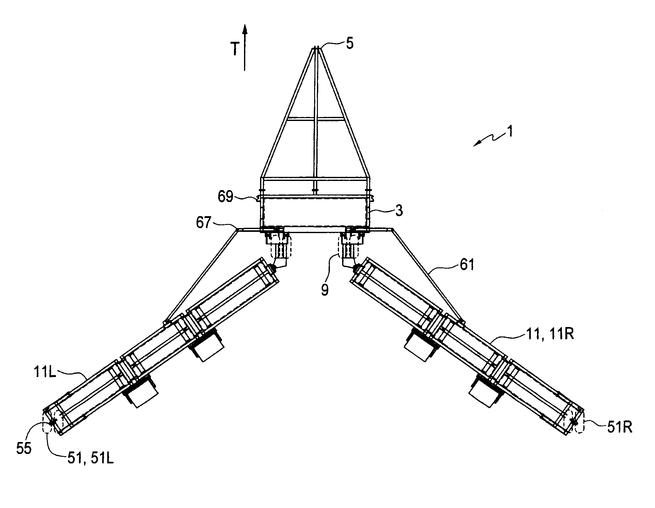
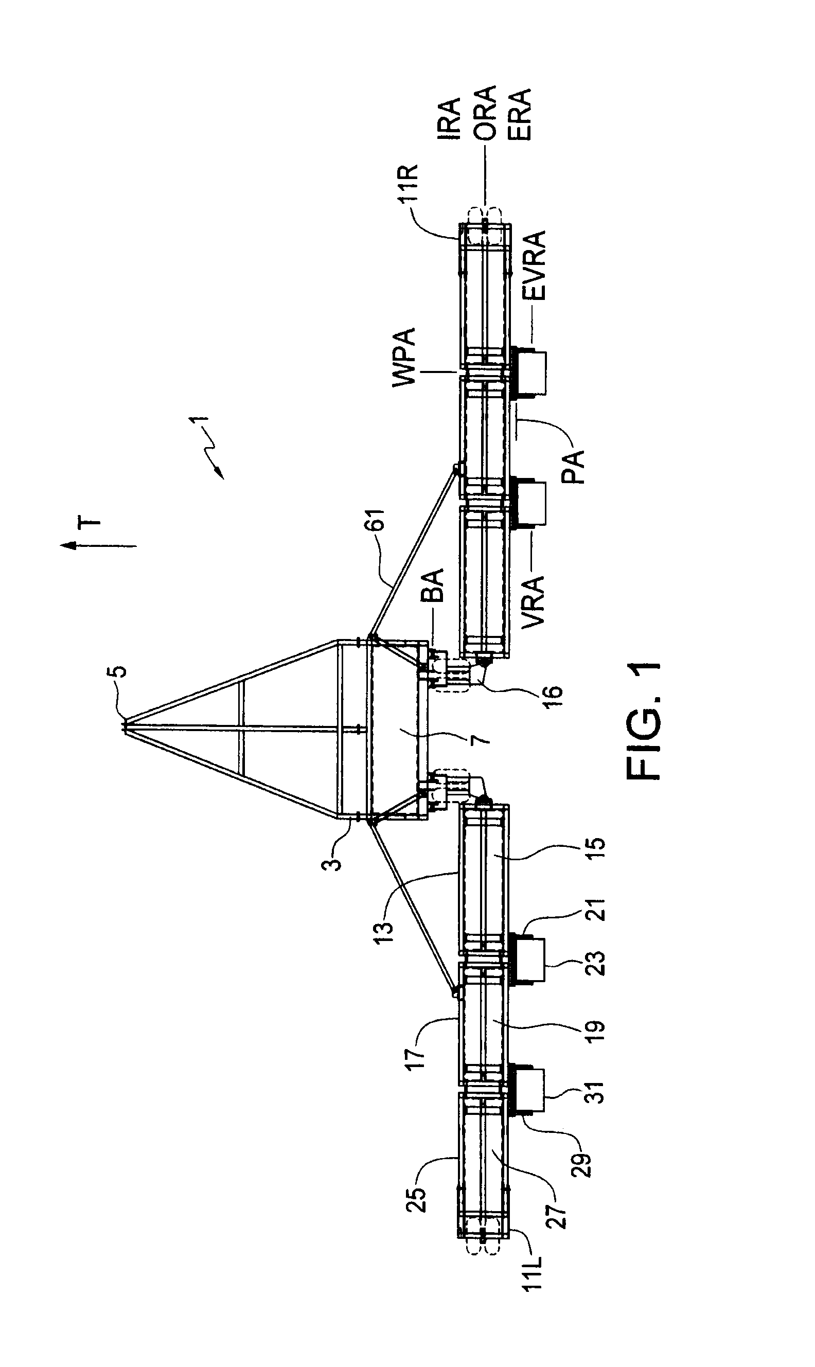
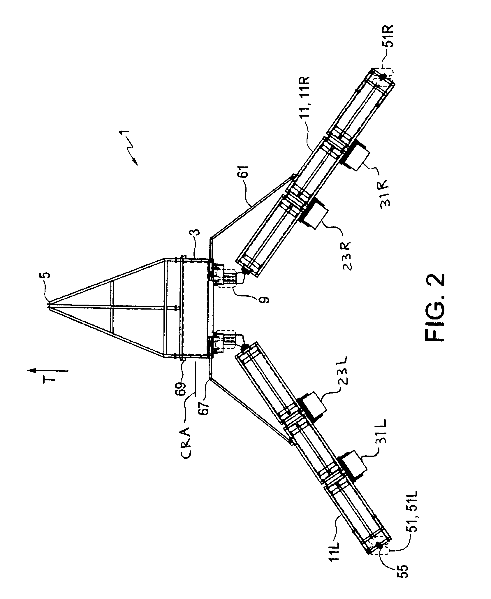
[0021]FIGS. 1-9 illustrate an embodiment of a land roller implement apparatus 1 of the present invention. The apparatus 1 comprises a center section comprising a center frame 3, a hitch 5 at a front end of the center frame 3 adapted for attachment to a towing vehicle, and a center roller 7 rotatably mounted to the center frame 3 about a center roller rotational axis CRA oriented substantially perpendicular to an operating travel direction T. Center wheels 9 mounted on the center frame 3 are movable from a raised operating position to a lowered transport position supporting the center roller 7 above the ground for movement in the operating travel direction T.

[0022]Right and left wings 11R, 11L are pivotally mounted to corresponding right and left sides of the center frame 3. Each wing 11 comprises inner, outer, and extension, wing frames. The inner wing frame 13 is pivotally mounted to a corresponding side of the center frame 3, and an inner roller 15 is rotatably mounted to the inne...


PUM


Abstract

A land roller implement has a center frame and a center roller. Wings are pivotally mounted to a wing bracket pivotally mounted to, and extending rearward from, each side of the center frame. The wings and center frame thus move independently up and down when operating. The bracket is locked and wheels mounted on the brackets move the rollers up for transport. Inner and outer rollers on each wing are aligned and separated by a roller spacing. An overlap roller rolls over the spacing. In transport position the right and left wings extend rearward from the center frame and right and left overlap rollers are aligned with, and adjacent to, each other. During a turn, the wings pivot and move closer to each other. To avoid contact with each other the right and left overlap rollers move forward and rearward to offset positions.

Description

[0001]This invention is in the field of agricultural implements and in particular a folding land rolling and packing implements.BACKGROUND[0002]Land rollers or packers are used in agriculture to pack seed, level land, push rocks down into the soil, break up clods, and for like purposes. What are commonly called land rollers comprise a fairly large diameter cylindrical steel roller rotatably mounted to a frame such that the rotational axis of the roller is oriented perpendicular to the operating travel direction. Land packing implements comprise a packing element with a generally cylindrical shape that may be defined by a coil as in FIG. 12 of U.S. Pat. No. 4,896,732 to Stark, or by a series of packer wheels mounted close together on a common shaft as in FIG. 1 of the Stark patent. For convenience both rollers and packers will be referred to hereafter as land rollers or land rolling implements.[0003]These rollers have a relatively low draft since they are not engaging the soil but si...

Claims


Application Information

Patent Timeline
Patent Type & Authority Applications(United States)
IPC IPC(8): A01B73/04A01B63/16
CPCA01B73/067A01B29/02
Inventor HULICSKO, LES
Owner RITE WAY MFG
Why Eureka
Try Eureka