
Method for correcting the trajectory of terminally guided ammunition

a terminally guided and trajectory technology, applied in the field of projectile imprinting, can solve the problem of insufficient information alone, and achieve the effect of effective use of projectiles

Inactive Publication Date: 2010-12-09
OERLIKON CONTRAVES BESCHRAENKTER HAFTUNG
View PDF32 Cites 20 Cited by
  • Summary
  • Abstract
  • Description
  • Claims
  • Application Information

AI Technical Summary

Benefits of technology

[0012]It is an object of the invention to provide a method which permits an effective use of projectiles during an optimal engagement of the target.

Problems solved by technology

While it can measure the earth's magnetic field and determine the magnetic field lines, this information alone is not sufficient, since the direction of the magnetic field line on the one hand depends on the position on the globe and on the other hand on the direction of the ballistic trajectory line of fire.

Method used


Image

  • Method for correcting the trajectory of terminally guided ammunition
  • Method for correcting the trajectory of terminally guided ammunition

Examples


Embodiment Construction

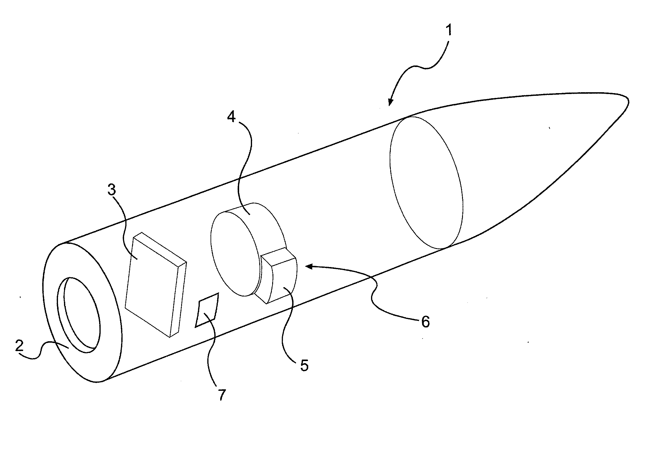
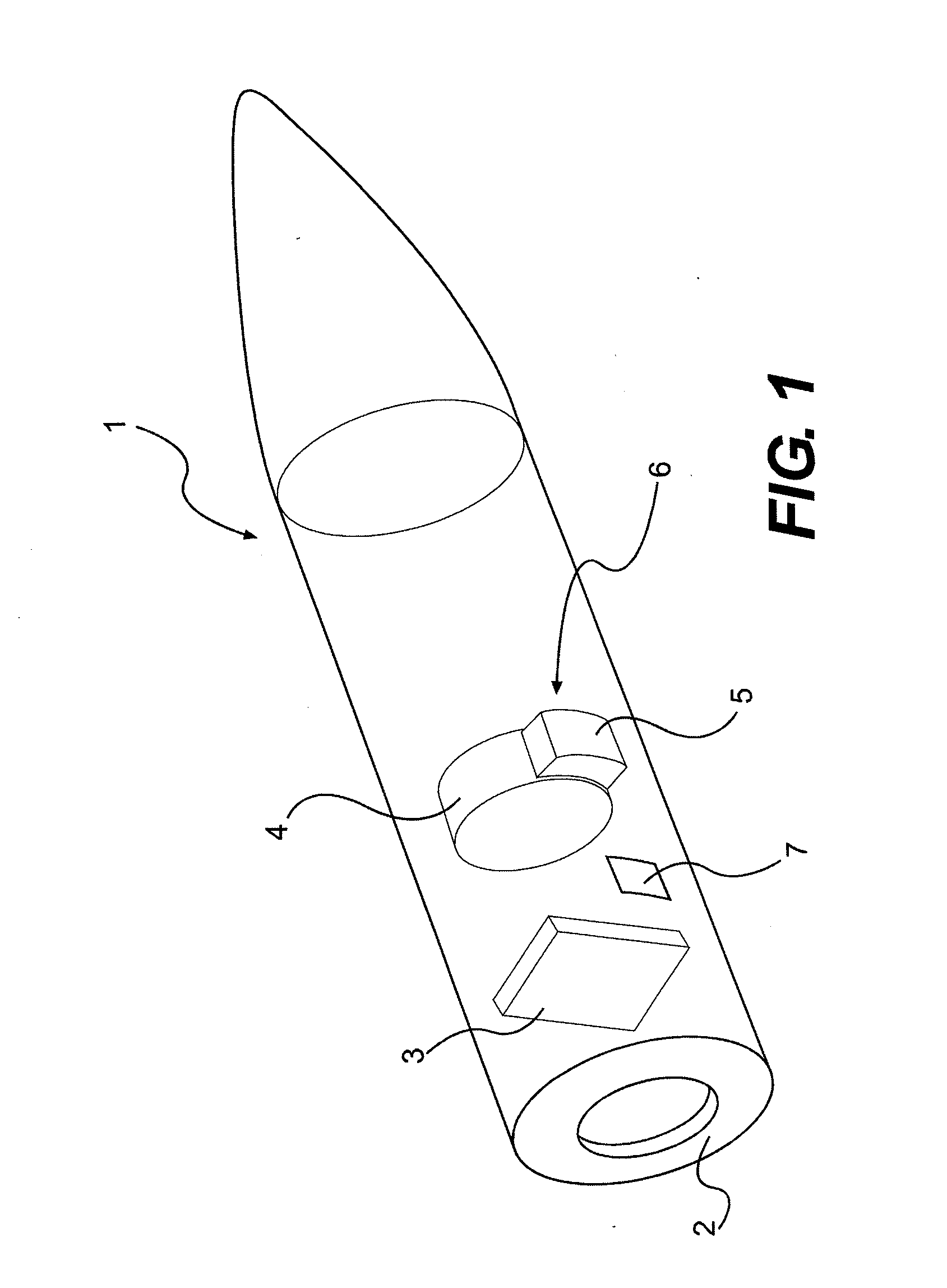
[0018]The only FIGURE shows the essential parts of a projectile 1 for the implementation of the idea. In this example, the projectile incorporates a tail sensor 2, a magnetic field sensor 3, explosives 4, as well as at least an ejection element 5, as a correction impulse propulsion unit 6. 7 identifies an analysis device which is functionally connected to the other assemblies.

[0019]The function is as follows:

[0020]The magnetic sensor 3 recognizes the rotational speed (roll rate) of the projectile 1 and the direction of the magnetic field relative to projectile 1. Through the previously determined declination angles of the earth's magnetic field from the vertical direction of the earth's gravity field, the geostationary roll attitude of projectile 1 can be determined in the analysis device 7. Via the now carried out “imprinting”, for example when projectile 1 passes the muzzle, projectile 1 or the analysis unit 7, respectively, during flight recognizes its individual deviation using ...


PUM


Abstract

A method for correcting a trajectory of terminally guided ammunition is provided. In order to achieve a high probability of hits, in particular when firing in bursts (continuous fire, rapid single shot fire), it is provided that every individual ammunition is addressed separately. The “imprinting” is performed based on the beam rider guidance principle of terminally guided ammunition. Every individual ammunition reads only the guidance beam identified for this ammunition and can, using additional information, determine its absolute roll attitude in space in order to achieve the proper triggering of the correcting propulsion unit.

Description

[0001]This nonprovisional application claims priority under 35 U.S.C. §119(a) to German Patent Application No. DE 10 2009 024 508.1, which was filed in Germany on Jun. 8, 2009, and which is herein incorporated by reference.BACKGROUND OF THE INVENTION[0002]1. Field of the Invention[0003]The invention relates to projectile imprinting, in particular for terminally guided projectiles or ammunition in the medium caliber range.[0004]2. Description of the Background Art[0005]Guidance in the terminal phase for ammunition fired from a barrel of a weapon is subject to limitations due to various loads during firing. Sensor and guidance elements must have a robust design. In addition, the volume in medium caliber ammunition for installation is limited. Seeker heads with their inertial sensors, in particular, cannot always be housed, especially in medium caliber ammunition, as a payload must also be carried. Therefore space-saving technologies are used, for which semi-active methods have been de...

Claims


Application Information

Patent Timeline
IPC IPC(8): F42B15/01
CPCF41G7/266G05D1/108F41G7/305
Inventor SEIDENSTICKER, JENS
Owner OERLIKON CONTRAVES BESCHRAENKTER HAFTUNG
Learn More