Stator Manufacturing Method for a Motor and Stator Utilizing the same

a manufacturing method and stator technology, applied in the direction of manufacturing stator/rotor body, magnetic circuit shape/form/construction, windings, etc., can solve the problems of high cost and assembly difficulty, inconvenience in manufacturing, and complex procedures above, so as to reduce axial height, easy assembly, and low cost

Inactive Publication Date: 2010-12-09
SUNONWEALTH ELECTRIC MACHINE IND
View PDF6 Cites 9 Cited by
  • Summary
  • Abstract
  • Description
  • Claims
  • Application Information

AI Technical Summary

Benefits of technology

[0025]The stator above may omit the conventional silicon steel plates required for manufacturing a conventional stator. Therefore, advantages such as lower cost and reduced axial height, easy assembly and stable operation and so on are provided.

Problems solved by technology

As described above, manufacturing inconvenience is caused as each silicon steel plate 81 has to be individually formed by the punching process.
The procedures above are very complex and have some problems such as high cost and assembly difficulty.
This results in a space limit for the winding of the coil unit 84.
As a result, when the stator 80 is used in a motor, the torque and rotational speed of the motor can not be efficiently increased.
Based on the structure, it would be difficult to wind the coil unit 84 around the silicon steel entity along an inner peripheral surface thereof.
Therefore, the cost of assembly is increased and the assembly time is prolonged.
Furthermore, the stator 80 might have poorer quality if the coil unit 84 is accidentally scratched (or damaged) during the assembly.
Due to the difficulty in reducing the axial height, the conventional stator 80 no longer fits to the need of current design requirement as the modern available motors have a tendency towards a miniature design.
In such a case where the stator 80 is used in a motor, the axial height of the motor cannot be efficiently reduced, leading to a difficulty in implementing a miniaturized motor.
However, although the stator 90 has a flexible winding for the coil 92, the stator 90 still has drawbacks such as inconvenient assembly as each magnetic conducting member 91 requires to be assembled one by one, causing an inconvenient assembly.
As a result, drawbacks of the aforementioned stator 80, such as high cost, difficulty in reducing axial height, unstable operation and so on, are still presented when using the stator 90.

Method used


Image

  • Stator Manufacturing Method for a Motor and Stator Utilizing the same
  • Stator Manufacturing Method for a Motor and Stator Utilizing the same
  • Stator Manufacturing Method for a Motor and Stator Utilizing the same

Examples


first embodiment

[0053]Referring to FIG. 3, a manufacturing method for a stator of an inner-rotor-type motor is disclosed according to the invention. The method comprises at least a preliminary step S11, a winding step S12, a rolling step S13 and a shaping step S14.

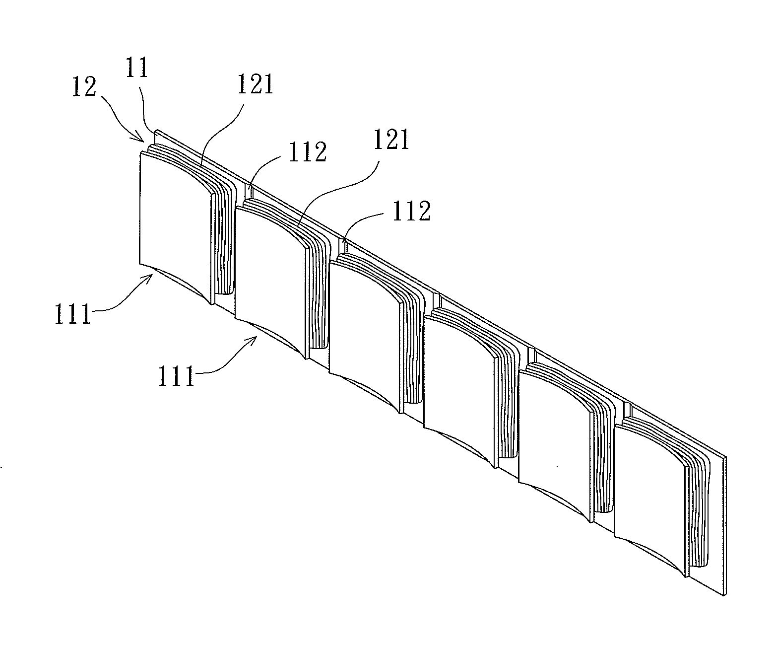
[0054]Referring to FIG. 4a, the preliminary step S11 is to provide a strip plate 11 preferably made of an insulation material in order to reduce the cogging torque. At least one wound portion 111 is formed on a surface of the strip plate 11. The at least one wound portion 111 may be integrally formed on the surface of the strip plate 11. Alternatively, the at least one wound portion 111 may also be independently manufactured in advance and then mounted on the surface of the strip plate 11 thereafter. Preferably, the strip plate 11 may be processed to form at least one groove 112 on the surface thereof, with the at least one wound portion 111 and the at least one groove 112 locating on the same surface for the subsequent rolling step S13. ...

second embodiment

[0063]Referring to FIG. 5, a manufacturing method for a stator of an outer-rotor-type motor is disclosed according to the invention. The method comprises at least a preliminary step S21, a winding step S22, a rolling step S23 and a shaping step S24.

[0064]Referring to FIG. 6a, the preliminary step S21 is to provide a strip plate 21. At least one wound portion 211 is formed on a surface of the strip plate 21. The strip plate 21 may be processed to form at least one groove 212 on another surface thereof, with the at least one wound portion 211 and the at least one groove 212 located on different surfaces. The details of the preliminary step S21 is the same as the previous preliminary step S11, so it's not described herein for brevity.

[0065]Also with reference to FIG. 6b, the winding step S22 is to provide a coil unit 22 comprising a plurality of coils 221, each being wound around an individual wound portion 211. The details of the winding step S22 is the same as the previous winding st...

third embodiment

[0081]Referring to FIG. 18, a stator of a motor comprises an unshaped sleeve 51 and a coil unit 52 according to the invention. The unshaped sleeve 51 is a rolled-up strip plate having a first coupling end 51a and a second coupling end 51b on two ends thereof. The unshaped sleeve 51 has a coupling portion where the first coupling end 51a and the second coupling end 51b are coupled with each other. The unshaped sleeve 51 has an outer peripheral surface 511 and an inner peripheral surface 512, with the outer peripheral surface 511 having a plurality of wound portions 513 extended therefrom. The wound portions 513 are wound with the coil unit 52 and may be evenly or unevenly spaced on the outer peripheral surface 511.

[0082]In the various embodiments previously disclosed, the first coupling ends 31a, 41a and 51a may be respectively coupled with the second coupling ends 31b, 41b and 51b by way of buckling as described in FIGS. 7 and 8. In addition, the wound portions 313, 413 and 513 are ...


PUM

PropertyMeasurementUnit
shapeaaaaaaaaaa
adhesionaaaaaaaaaa
magnetic fieldaaaaaaaaaa

Abstract

A stator manufacturing method for a motor comprises a preliminary step configured to provide a strip plate having at least one wound portion on a surface thereof; a winding step configured to provide a coil unit and wind the coil unit around the at least one wound portion of the strip plate; a rolling step configured to roll up the strip plate into an unshaped sleeve having a central hole, wherein the at least one wound portion and the coil unit are located inside the central hole; and a shaping step configured to shape the unshaped sleeve into a shaped sleeve.

Description

BACKGROUND OF THE INVENTION[0001]1. Field of the Invention[0002]The present invention generally relates to a stator manufacturing method for a motor and a stator utilizing the method and, more particularly, to a simplified stator manufacturing method for a motor and a stator utilizing the simplified method.[0003]2. Description of the Related Art[0004]The modern available stators are mainly categorized as two categories: the stators for inner-rotor-type motors and the stators for outer-rotor-type motors. Generally, the stators for both types of motors have substantially the same manufacturing procedures. Take the inner-rotor-type motors as an example, the stator structure and manufacturing method thereof will be illustrated.[0005]Please refer to FIG. 1, a stator manufacturing method for a stator 80 of a conventional motor comprises the following procedures. Firstly, a plurality of silicon steel plates 81 is formed by a punching process; and each of the silicon steel plates 81 is stac...

Claims


Application Information

Patent Timeline
Patent Type & Authority Applications(United States)
IPC IPC(8): H02K15/02H02K1/06
CPCH02K1/148Y10T29/49009H02K15/095
Inventor HORNG, ALEXYIN, TSO-KUO
Owner SUNONWEALTH ELECTRIC MACHINE IND
Why Eureka
Try Eureka