Localization Using Virtual Antenna Arrays In Modulated Backscatter RFID Systems

a virtual antenna array and backscatter technology, applied in direction finders using radio waves, multi-channel direction-finding systems using radio waves, instruments, etc., can solve the problem that the marker tags in the menache system do not maintain a known geometric relationship with respect, and achieve enhanced asset tracking, localization accuracy, and backscatter signals. enhanced

Inactive Publication Date: 2010-12-09
CHECKPOINT SYST INC
View PDF21 Cites 25 Cited by
  • Summary
  • Abstract
  • Description
  • Claims
  • Application Information

AI Technical Summary

Benefits of technology

[0016]When the tags are arranged on a tag in an array, a reader with a single element antenna can achieve localization accuracy similar to that achieved by a reader equipped with an antenna array of the same geometry and size as the tags in the array. The tags arranged in this manner can thus form a virtual antenna array tag, or a virtual array tag. A tag having a plurality of tags disposed upon it in this manner can be called a supertag. Virtual array tags can be used to enhance asset tracking. Furthermore, such virtual array tags disposed at known locations can also be used by a reader to localize itself.
[0017]The additional information provided by the different round trip travel times and the different phases of the backscatter signals permits enhanced accuracy in reading the backscatter signals. For example, it can permit enhanced accuracy in localizing the tags, in identifying an item associated with the tag device, and/or in localizing a reader relative to virtual array tags that are positioned at known locations to act

Problems solved by technology

However, in Menache the marker tags are distributed over a number of items, and are thus not disposed on a single tag device.

Method used


Image

  • Localization Using Virtual Antenna Arrays In Modulated Backscatter RFID Systems
  • Localization Using Virtual Antenna Arrays In Modulated Backscatter RFID Systems
  • Localization Using Virtual Antenna Arrays In Modulated Backscatter RFID Systems

Examples


Embodiment Construction

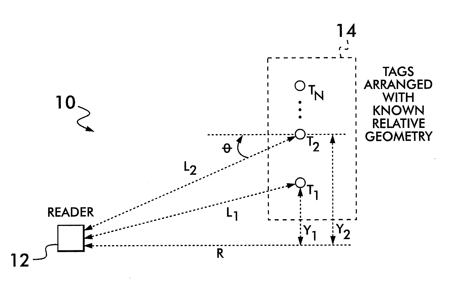
[0023]Referring now to FIG. 1, there is shown a schematic representation of the virtual antenna array system 10. The virtual antenna array system 10 includes a tag reader 12 and a virtual array tag 14. A plurality of tags T1-TN are disposed on the virtual array tag 14 in a manner know those skilled in the art, wherein the virtual array tag 14 can comprise any type of carrier device upon which the tags T1-TN may be disposed. The tags T1-TN are preferably single antenna tags. Although the individual tags T1-TN are shown arranged in a linear array, it will be understood that they can be disposed in any known geometric relationship with respect to each other. For example, the tags T1-TN can be fixed in a rectangular array, in an L-shape array, in a circular array, or in any other known geometries including other two dimensional geometries and three dimensional geometries.

[0024]The tag reader 12 can read two or more tags T1-TN within the virtual array tag 14. In the case where the tag re...


PUM


Abstract

A localization method for use in a tag communication system includes associating a supertag having a plurality of tags with an item, reading backscatter signals from the tags of the plurality of tags to provide a plurality of backscatter signals, estimating a signal parameter of the backscatter signals of the plurality of backscatter signals to provide a plurality of derived signal parameters, and localizing the item in accordance with the plurality of derived signal parameters. The backscatter signals are read by a tag reader having a single antenna and the item is localized in accordance with an antenna array technique performed upon the plurality of derived signal parameters. The backscatter signals are read with an antenna array to provide a further plurality of derived signal parameters for each tag of the plurality of tags, and the item is localized in accordance with the further pluralities of derived signal parameters.

Description

BACKGROUND OF THE INVENTION[0001]1. Field of Invention[0002]This invention relates to security tags and, more particularly, to localizing security tags and security tag readers.[0003]2. Description of Related Art[0004]U.S. Patent Publication No. 2002 / 0145563 A1, filed on Jan. 26, 2001 by Kane, discloses the use of time of arrival information and phase difference information in backscatter signals for precisely localizing a subject, and precisely monitoring the gait of the subject. In the Kane system the backscatter signals are produced by a plurality of RFID tags positioned at different locations on the body of the subject to be monitored. Additionally, Kane teaches a plurality of receiving antennas for receiving the signals from the tags on the body of the subject, and performing separate phase difference calculations.[0005]U.S. Pat. No. 7,009,561, issued on Mar. 7, 2006 to Menache, discloses an RF motion tracking system including a stationary RF transmitter and a plurality of stat...

Claims


Application Information

Patent Timeline
IPC IPC(8): G08B5/22
CPCG01S13/756G01S3/74
Inventor RAMCHANDRAN, KANNANWILD, BEN J.TKACHENCO, ARTEMMADHOW, UPAMANYU
Owner CHECKPOINT SYST INC
Why Eureka
Try Eureka