LED lamp heat dissipating module

a technology for heat dissipation modules and led lamps, which is applied in the direction of transportation and packaging, semiconductor devices for light sources, lighting and heating apparatus, etc., can solve the problems of increased maintenance and application costs, reduced heat dissipation efficiency, so as to improve the convenience of the assembling process

Inactive Publication Date: 2010-12-09
CELSIA TECH TAIWAN INC
View PDF2 Cites 46 Cited by
  • Summary
  • Abstract
  • Description
  • Claims
  • Application Information

AI Technical Summary

Benefits of technology

[0007]It is a primary objective of the present invention to provide an LED lamp heat dissipating module for transmitting the heat generated by an LED to a heat dissipating body quickly, so that the LED lamp can continue its operation at an appropriate working temperature and achieve the effects of extending the life expectancy and improving the cost-effectiveness and practicality of the LED lamp heat dissipating module.
[0009]Compared with the prior art, the present invention conducts a large quantity of heat by a phase change of a working fluid in the two flat heat pipes, and the heat generated by the LED is transmitted to the conducting base quickly. Since the contact area of the flat heat pipes and the heat dissipating body is large, therefore the heat can be conducted to the heat dissipating body uniformly, and then a heat sink with a large heat dissipating area is used to dissipate the heat, such that the LED lamp set can continue its operation at an appropriate working temperature. In addition, the present invention further comprises an embedding slot disposed at the periphery of the conducting base for facilitating the embedment of the heat dissipating module to the internal wall of the lamp house to improve the convenience of the assembling process.

Problems solved by technology

As the quantity of LEDs increases and the high power LED advances, the heat generated by the LED module gradually increases, and thus results in a shorter life expectancy of an LED lamp and higher maintenance and application cost, if the heat cannot be dissipated timely.
Since the heat transmission is achieved by a contact conduction method, the conduction path is relatively long, the heat conduction is relatively non-uniform, and the heat dissipation speed is relatively slow.
Obviously, the heat dissipating efficiency of this method is insufficient for the high power LED.

Method used


Image

  • LED lamp heat dissipating module
  • LED lamp heat dissipating module
  • LED lamp heat dissipating module

Examples


Embodiment Construction

[0015]The technical characteristics, features and advantages of the present invention will become apparent in the following detailed description of preferred embodiments with reference to the accompanying drawings, and the preferred embodiments are used for illustrating the present invention only, but not intended to limit the scope of the invention.

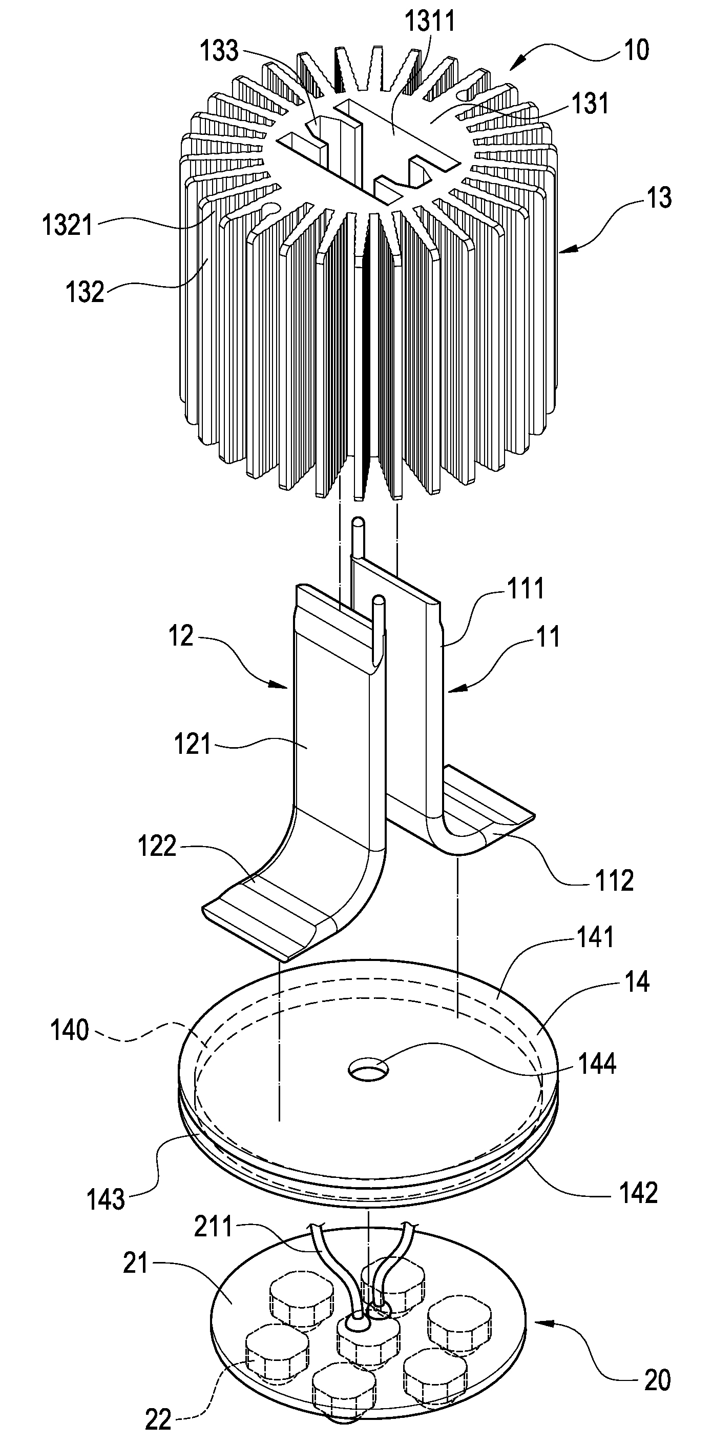
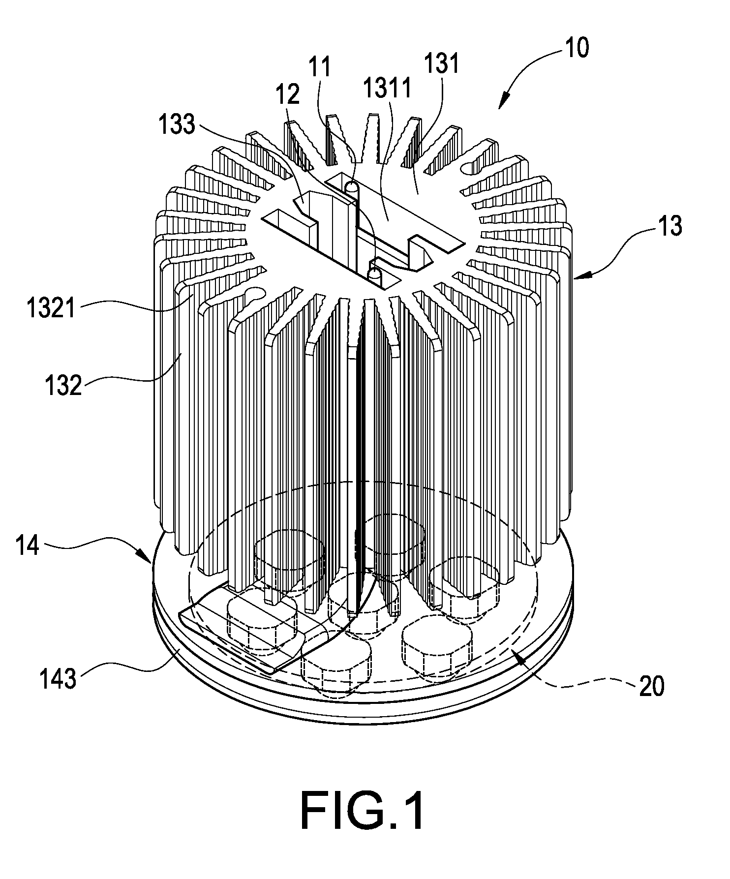
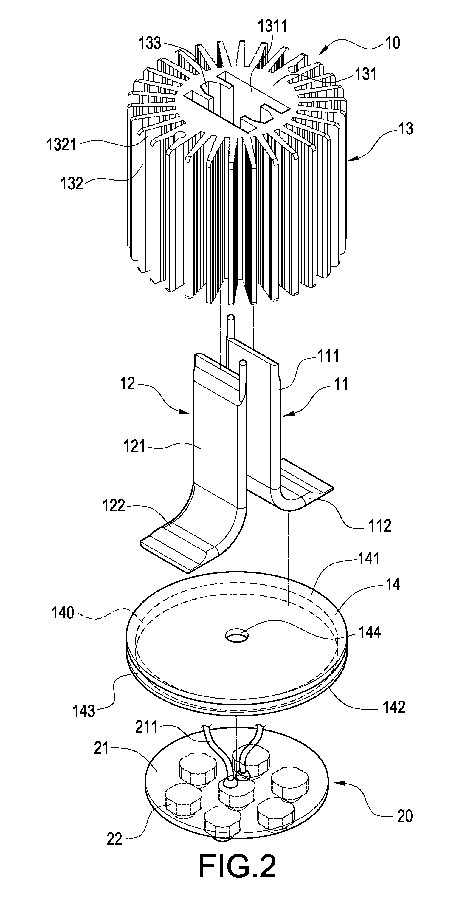
[0016]With reference to FIGS. 1 and 2 for a perspective view and an exploded view of the present invention respectively, the present invention provides an LED lamp heat dissipating module 10 for dissipating heat of an LED light emitting element 20, and the LED lamp heat dissipating module 10 comprises at least two flat heat pipes 11, 12, a heat dissipating body 13 and a conducting base 14.

[0017]The two flat heat pipes 11, 12 are substantially L-shaped, and each has a condensation section 111, 121 and an evaporation section 112,122, wherein each evaporation section 112, 122 is a bent section, and the two bent sections are disposed outward...


PUM


Abstract

A heat dissipating module embedded into an LED lamp house for dissipating heat of an LED light emitting element includes two flat heat pipes, a heat dissipating body and a conducting base. The heat dissipating body includes a cylindrical pillar, heat sinks radially formed around the cylindrical pillar, two longitudinal through grooves at the cylindrical pillar for passing a condensation section of the flat heat pipe. The conducting base includes corresponding first and second surfaces, and the first surface is attached to an evaporation section of the flat heat pipe, and the second surface is attached to the LED light emitting element. The conducting base perpendicular to an axis of the cylindrical pillar includes an embedding slot for embedding the heat dissipating module into an internal wall of the lamp house, such that the heat dissipating module can quickly dissipate the heat generated by the LED light emitting element.

Description

BACKGROUND OF THE INVENTION[0001]1. Field of the Invention[0002]The present invention relates to a heat dissipating apparatus, and more particularly to a heat dissipating module installed to a light emitting diode (LED) lamp.[0003]2. Description of Prior Art[0004]Since light emitting diode (LED) features a low power consumption, a long life expectancy, a small volume and a quick response, it gradually replaces traditional light bulbs and is used extensively in various different light emitting devices. To increase the illumination range and brightness of an LED, a plurality of LEDs are combined into an LED module. As the quantity of LEDs increases and the high power LED advances, the heat generated by the LED module gradually increases, and thus results in a shorter life expectancy of an LED lamp and higher maintenance and application cost, if the heat cannot be dissipated timely.[0005]To dissipate the high heat generated by the LED lamp, most LED lamp sets install a heat dissipating...

Claims


Application Information

Patent Timeline
Patent Type & Authority Applications(United States)
IPC IPC(8): F21V29/00
CPCF21K9/00F21V29/004F21V29/89F21Y2101/02F21V29/773F21V29/006F21V29/51F21Y2115/10
Inventor MEYER, IV, GEORGE ANTHONYSUN, CHIEN-HUNGCHEN, CHIEH-PING
Owner CELSIA TECH TAIWAN INC
Why Eureka
Try Eureka