
Adjustable unloader valve

a technology of unloader valve and adjustment device, which is applied in the direction of valve housing, positive displacement liquid engine, machine/engine, etc., can solve the problems of unloader valve not allowing coupling, prior art unloader valve and related “regulating” device limited, and extreme adjustmen

Inactive Publication Date: 2010-12-09
KARCHER NORTH AMERICA INC
View PDF13 Cites 3 Cited by
  • Summary
  • Abstract
  • Description
  • Claims
  • Application Information

AI Technical Summary

Benefits of technology

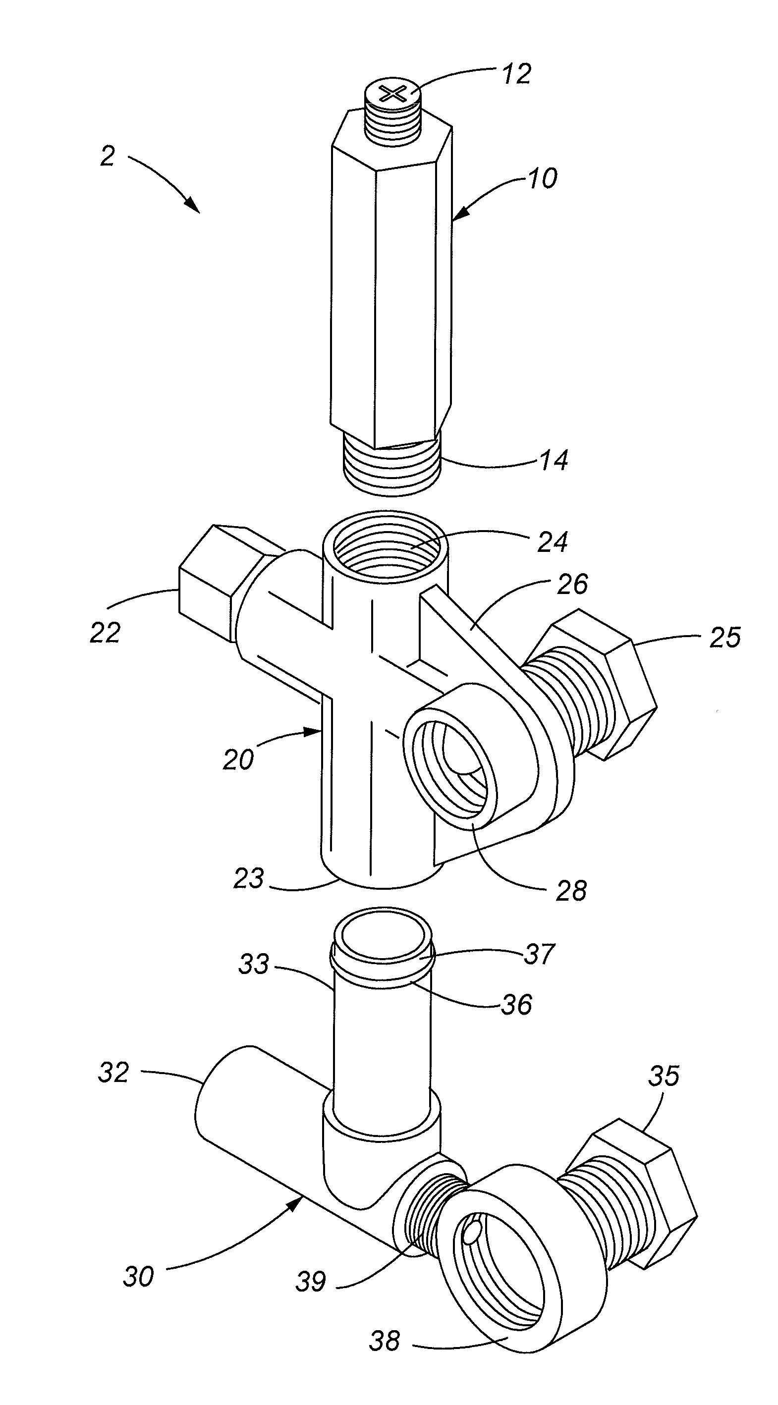
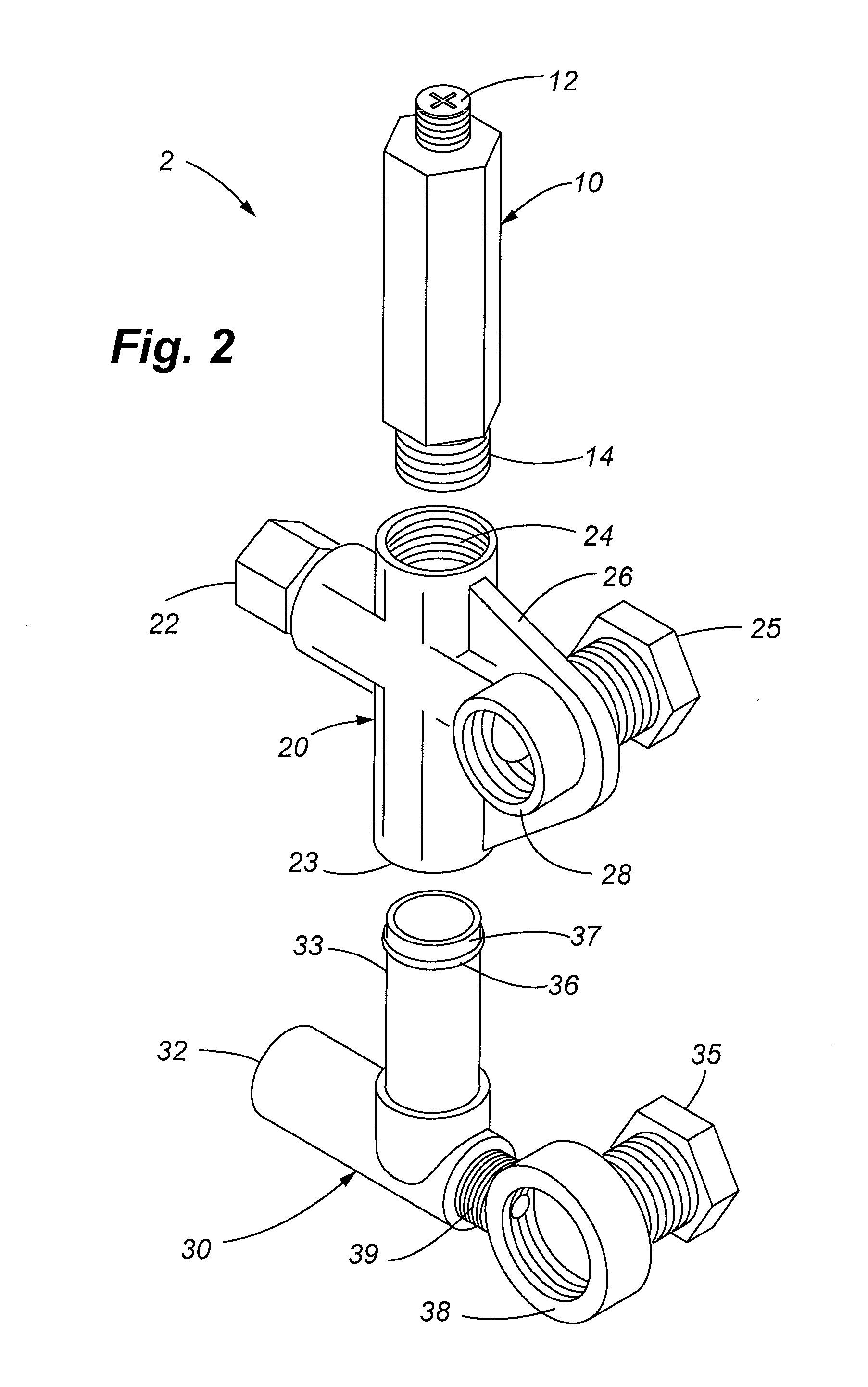
[0005]The unloader valve of the present disclosure solves these and other problems associated with the prior art by providing an unloader valve assembly having inlet and outlet connections or “couplings”, capable of connecting with the respective outlets and inlets of a variety of different sized pumps, and where the locations of the couplings of the unloader valve assembly are adjustable about two axes or dimensions to allow the unloader valve to adapt to a wide variety and size of high pressure pumps and / or similar equipment. The unloader valve assembly of the present disclosure accomplishes this in part by incorporating an outlet or first coupling, which is fixed to the unloader valve assembly, and an associated inlet or second coupling, both of which are adjustable about both a first axis and a second axis. This adjustability permits the location of the second coupling to be adjusted or modified with respect to the location of the first coupling. The ability of the second coupling to adjust about a first and second axis (both vertically and horizontally) further permits the unloader valve assembly to be used with a wide variety of sizes and types of pumps, and in particular high pressure pumps.

Problems solved by technology

As a result of their custom nature, such unloader valves known in the prior art are extremely sensitive to adjustment, and also sensitive to the precise sizing and locations of couplings of the unloader valve to the particular pump.
Prior art unloader valves and related “regulating” devices are limited in the variety and types of pumps and high pressure pumps that they accommodate.
More specifically, if the inlet and outlet for the pump are not aligned within the range of locations of the fittings for the particular pumps requiring the unloader valve, the unloader valve will not allow coupling with and therefore will not function with the particular pump.
Thus, these prior art unloader valves do not accommodate a wide variety of different sized high pressure pumps and other similar devices, and generally experience other problems associated with prior art unloader valves.

Method used


Image

  • Adjustable unloader valve
  • Adjustable unloader valve
  • Adjustable unloader valve

Examples


Embodiment Construction

[0025]As described in detail below, various embodiments of the present disclosure include a novel valve, comprising an inlet connection or coupling and an outlet connection or coupling, the outlet coupling further comprising adjustment means, and the valve comprising an unloader valve for regulating the flow of water returning to a pump or similar device, and / or other features.

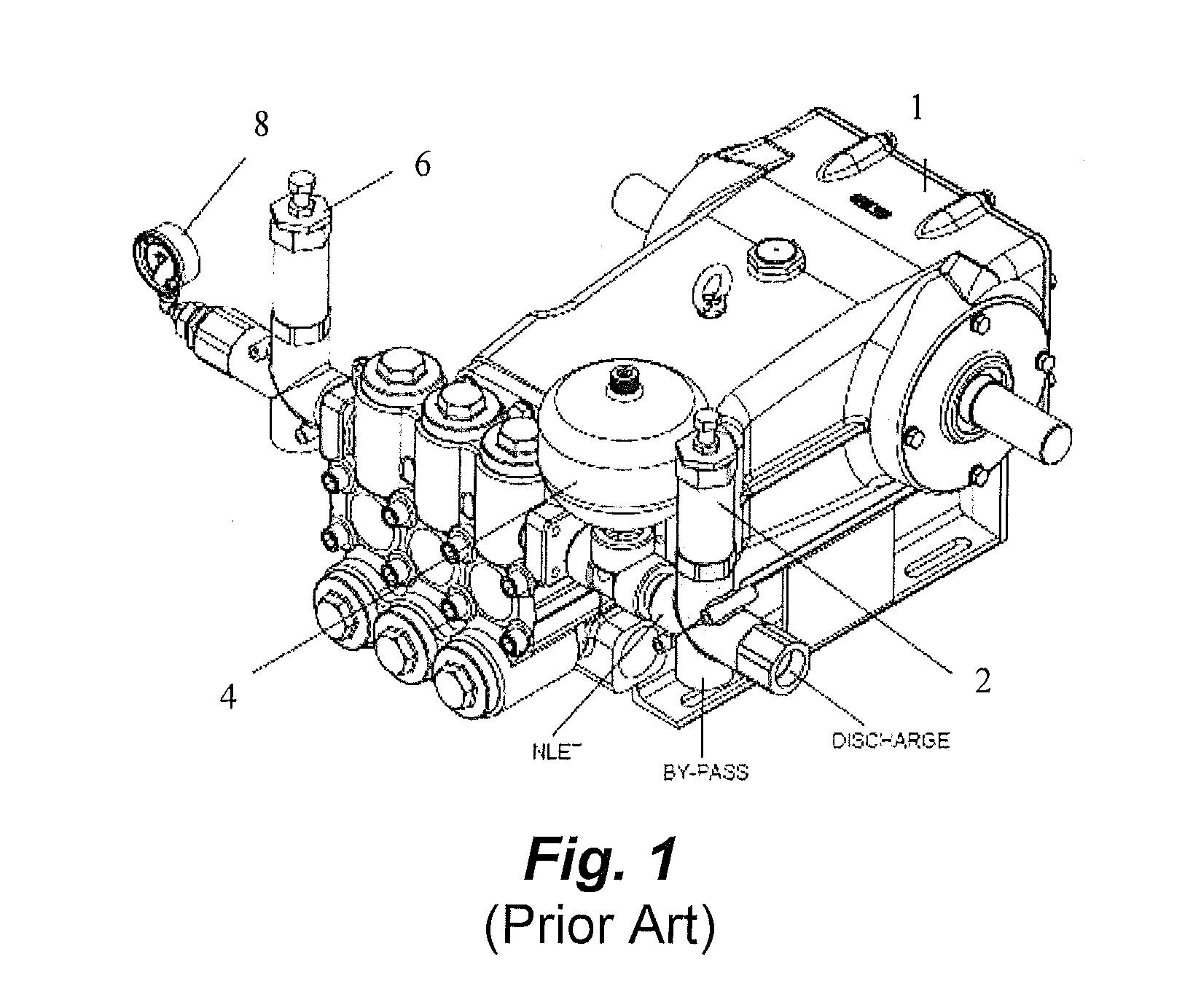
[0026]Referring now to the drawing figures, FIG. 1 shows a prior art unloader valve and pump assembly. This assembly comprises a fluid pump 1, a pressure sensitive unloader valve 2, a pulsation dampener 4, a relief valve 6 and pressure gauge 8. As shown in FIG. 1, the inlet of the prior art unloader valve 2 is coupled to an outlet of the pump 1 and the bypass of the unloader valve remains open or uncoupled. In other prior art embodiments, the bypass may be coupled to an inlet (not shown) of the pump 1. The unloader valve 2 includes a discharge which permits fluid to exit the unloader valve 2 once a sensitive o...


PUM


Abstract

A pressure unloader valve is disclosed having inlet and outlet connections adjustable about two dimensions to adapt to a wide variety of high pressure pumps and similar equipment associated with such applications. According to one embodiment, the inlet and outlet connections are adjustable about both a horizontal and a vertical axis. A method for regulating pressure in a valve and pump assembly is also disclosed.

Description

FIELD OF THE INVENTION[0001]The present disclosure is related to valves and regulators, and more specifically a high pressure unloader valve having inlet and outlet connections adjustable about two dimensions to adapt to a wide variety of high pressure pumps and similar equipment associated with such applications.BACKGROUND OF THE INVENTION[0002]Unloader valves or “regulators”, as they are sometimes referred to, direct the flow of water exiting a pump. In particular, unloader valves are designed to redirect the flow of water from the outlet of the pump, through the unloader valve, and back to the inlet side of the pump to prevent dangerously high pressure from building in the pump, and when activated through a separate outlet or exhaust. Unloader valves are often required for high pressure pumping applications for quickly and efficiently regulating excess pressure created by the high pressure pump. Types of unloader valves include “trapped pressure” valves, which are activated by bu...

Claims


Application Information

Patent Timeline
Patent Type & Authority Applications(United States)
IPC IPC(8): F04B49/22F16K15/00
CPCF04B49/08F16K27/0263F04B49/225Y10T137/7837
Inventor GONZALEZ CHAPA, GERARDO ANGEL
Owner KARCHER NORTH AMERICA INC
Learn More