Method and installation for applying foil material onto successive sheets

a foil material and installation method technology, applied in the field of security documents, can solve the problems of not being suited to applying small-sized patches of foil material, being rather difficult to implement, and being difficult to install

Inactive Publication Date: 2015-03-03
KBA NOTASYS SA
View PDF42 Cites 5 Cited by
  • Summary
  • Abstract
  • Description
  • Claims
  • Application Information

AI Technical Summary

Benefits of technology

[0021]A further aim of the present invention is to provide a solution that allows application of foil material in a precise manner onto the sheets.
[0022]Still another aim of the present invention is to provide a solution that allows application of foil material onto the sheets without this affecting further processing of the said sheets in the downstream processes.
[0023]Yet another aim of the present invention is to provide a solution that is capable of applying a wide range of sizes of portions of foil material onto the sheets.
[0033]The present invention is in particular applicable to cover windows or openings cut into the sheets prior to the application of the continuous band or bands of foil material. In this case in particular, it is advantageous to apply a foil material that is substantially transparent.

Problems solved by technology

WO 2004 / 096541 A1 has been found to be rather difficult to implement as it requires precise cutting and positioning of the cut strips of laminate with respect to the sheets.
WO 2004 / 096541 A1 is furthermore only applicable for strips of laminate having a minimum length and is in particular not suited for applying small-sized patches of foil material onto the sheets.
A difficulty however arises in connection with the evacuation of the waste portions of the continuous band or bands of foil material that are not to remain on the sheets.
Such difficulty is exacerbated in the case of cutting of the foil material by means of a laser since specific means need to be provided to carry out such evacuation.

Method used


Image

  • Method and installation for applying foil material onto successive sheets
  • Method and installation for applying foil material onto successive sheets
  • Method and installation for applying foil material onto successive sheets

Examples


Embodiment Construction

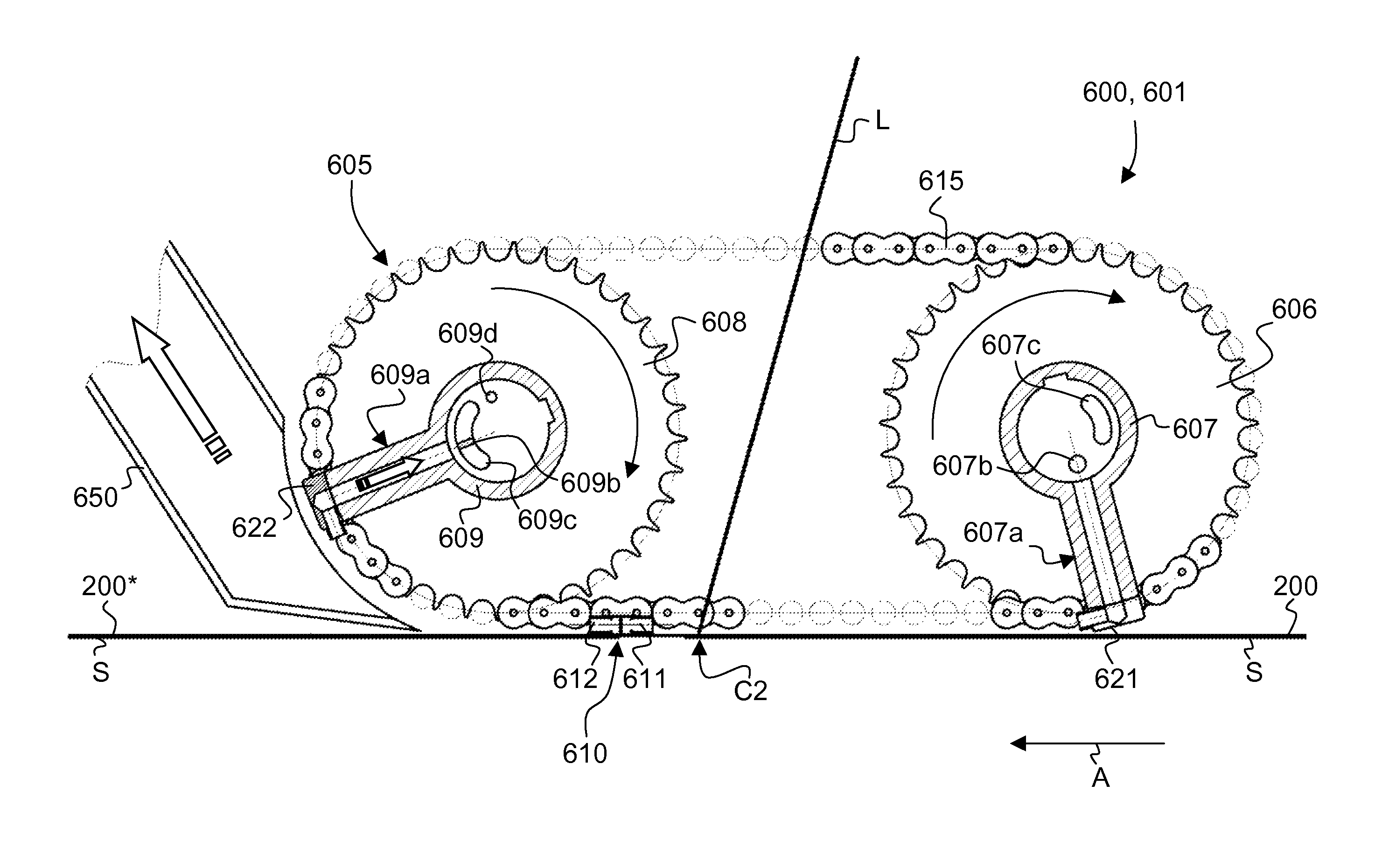
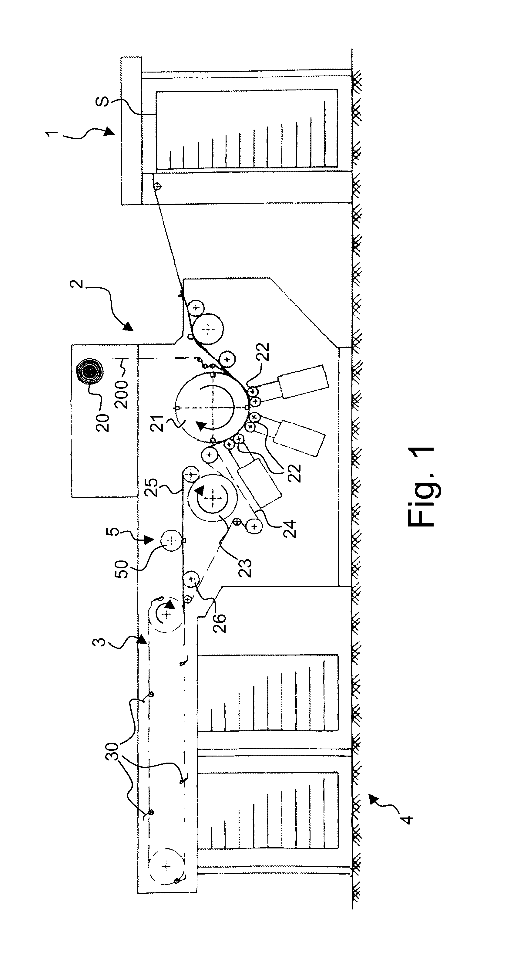
[0048]FIG. 1 is a schematic side view of a sheet-fed processing machine for applying foil material onto successive sheets as discussed in European patent application No. 07103051.4 and International application No. PCT / IB2008 / 050626 discussed hereabove. The configuration thereof is almost identical to the hot-foil stamping machines of the prior art, as for instance disclosed in International applications nos. WO 97 / 35721 A1, WO 97 / 35794 A1, WO 97 / 35795 A1 and WO 97 / 36756 A1, the disclosures of which are incorporated herein by reference. It comprises a sheet-by-sheet feeding station 1 for feeding individual sheets S to a foil application unit 2, which foil application unit 2 basically comprises an application cylinder 21 (in this case a four-segment cylinder having four segments each capable of seizing and transporting a sheet coming from the sheet-by-sheet feeding station 1) that cooperates with a plurality of rows of pressure rollers 22 which are pressed resiliently against the cir...


PUM

PropertyMeasurementUnit
displacementaaaaaaaaaa
distanceaaaaaaaaaa

Abstract

There is described a method for applying foil material (200) onto successive sheets (S), especially sheets for the production of securities, such as banknotes. In a first step, individual sheets (S) are transported in succession along a sheet transport path. In a second step, at least one continuous band of foil material (200) is applied onto the individual sheets (S) along a direction substantially parallel to a direction of displacement (A) of the individual sheets, thereby forming a continuous flow of sheets linked to one another by the said at least one continuous band of foil material (200). In a third step, the said at least one continuous band of foil material (200) is cut by means of a laser beam (L) such that the continuous flow of sheets is again separated into individual sheets (S) with portions of foil material (200*) remaining on the sheet. The cutting is performed at positions located on the sheets (S) such that said portions of foil material (200*) remaining on the sheets do not extend beyond leading and trailing edges of the sheets (S). Waste portions (205) of said at least one continuous band of foil material (200) that are not to remain on the sheets (S) are seized prior to cutting by the laser beam (L) and are held throughout the cutting process. There is also described an installation for carrying out the above method.

Description

TECHNICAL FIELD[0001]The present invention generally relates to a method and installation for applying foil material onto successive sheets, especially sheets for the production of securities. The present invention is especially applicable in the context of the production of security documents, such as banknotes.BACKGROUND OF THE INVENTION[0002]The application of foil material onto sheets, especially sheets for the production of securities, is as such already well-known in the art. Such application is typically aimed at providing securities with additional security elements, such as in particular so-called OVD's (Optically Variable Devices). OVD's typically take the form of a patch or foil laminate comprising an optically-diffractive layer (usually a metallized layer) producing optically variable effects. OVD's are in particular known under the name of KINEGRAM®, which is a registered trademark of OVD Kinegram AG, a member of the Leonhard Kurz Group.[0003]OVD's are typically supplie...

Claims


Application Information

Patent Timeline
Patent Type & Authority Patents(United States)
IPC IPC(8): B32B38/00B32B38/10B32B38/04B32B37/00B32B37/22B42D15/00B44C1/17
CPCB32B38/0004B32B37/22B42D15/0013B44C1/1729B32B37/0046B32B2310/0843B32B2429/00B42D2031/28B42D2031/30B42D25/29B42D25/47B42D25/475Y10T156/1084Y10T156/12Y10T156/1304Y10T156/1317Y10T156/1343
Inventor EITEL, JOHANN EMILGYGI, MATTHIASNAGLER, KURT GEORG
Owner KBA NOTASYS SA
Why Eureka
Try Eureka