Systems and methods for through-the-earth communications

a technology of wireless communication and earth formation, applied in the direction of superconducting magnets/coils, pulse techniques, magnetic bodies, etc., can solve the problems of insufficient development of fully wireless communications technology, and inability to provide two-way communication through earth to mines or tunnels of any useful depth, etc., to achieve the effect of reducing physical length

Inactive Publication Date: 2010-12-09
MARSHALL RADIO TELEMETRY
View PDF37 Cites 27 Cited by
  • Summary
  • Abstract
  • Description
  • Claims
  • Application Information

AI Technical Summary

Benefits of technology

[0010]The present invention also includes methods for tuning a radiating antenna used underground. The act of tuning includes positioning a radiating antenna that has a reduced physical length relative to a corresponding, above-ground resonant length for a predetermined carrier frequency, at an underground location. The electric length of the radiating antenna is then adjusted, or tuned, without increasing its physical length beyond the above-ground resonant length to cause the antenna to resonate at the predetermined carrier frequency. In various embodiments, when processes of the present invention are used to tune a radiating antenna underground, the radiating antenna may transmit and / or receive electromagnetic waves having a wide range of frequencies, including, without limitation, frequencies in the range of about 100 kHz to about 1 MHz, frequencies of up to about 1.8 MHz, and even frequencies of up to about 140 MHz.

Problems solved by technology

Yet, the prior art has not reached the point of providing two-way communication through the earth to mines or tunnels of any useful depth.
However, on Jan. 10, 2009 MSHA stated that “fully wireless communications technology is not sufficiently developed at this time, nor is it likely to be technologically feasible by Jun. 15, 2009.”

Method used


Image

  • Systems and methods for through-the-earth communications
  • Systems and methods for through-the-earth communications
  • Systems and methods for through-the-earth communications

Examples


Embodiment Construction

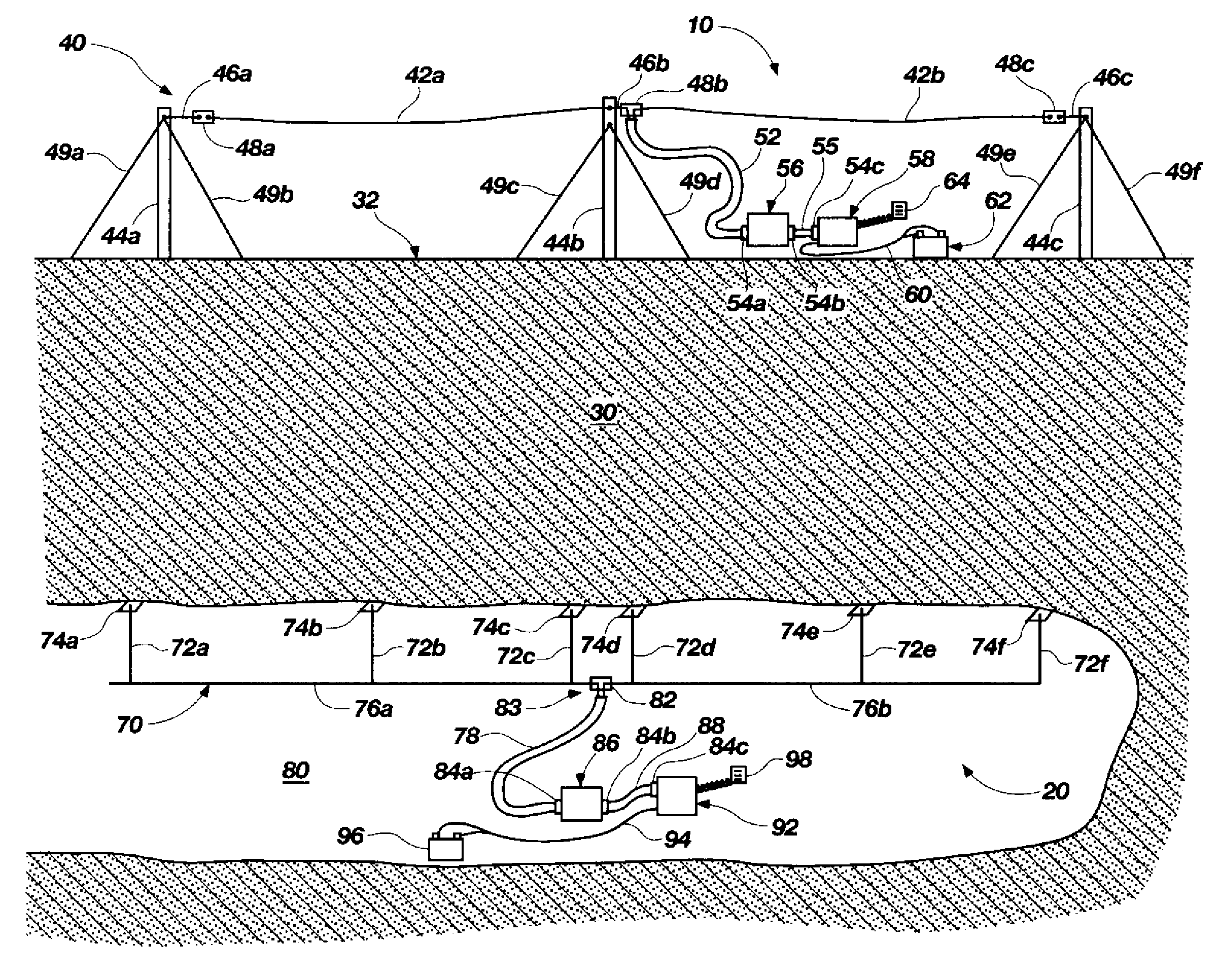
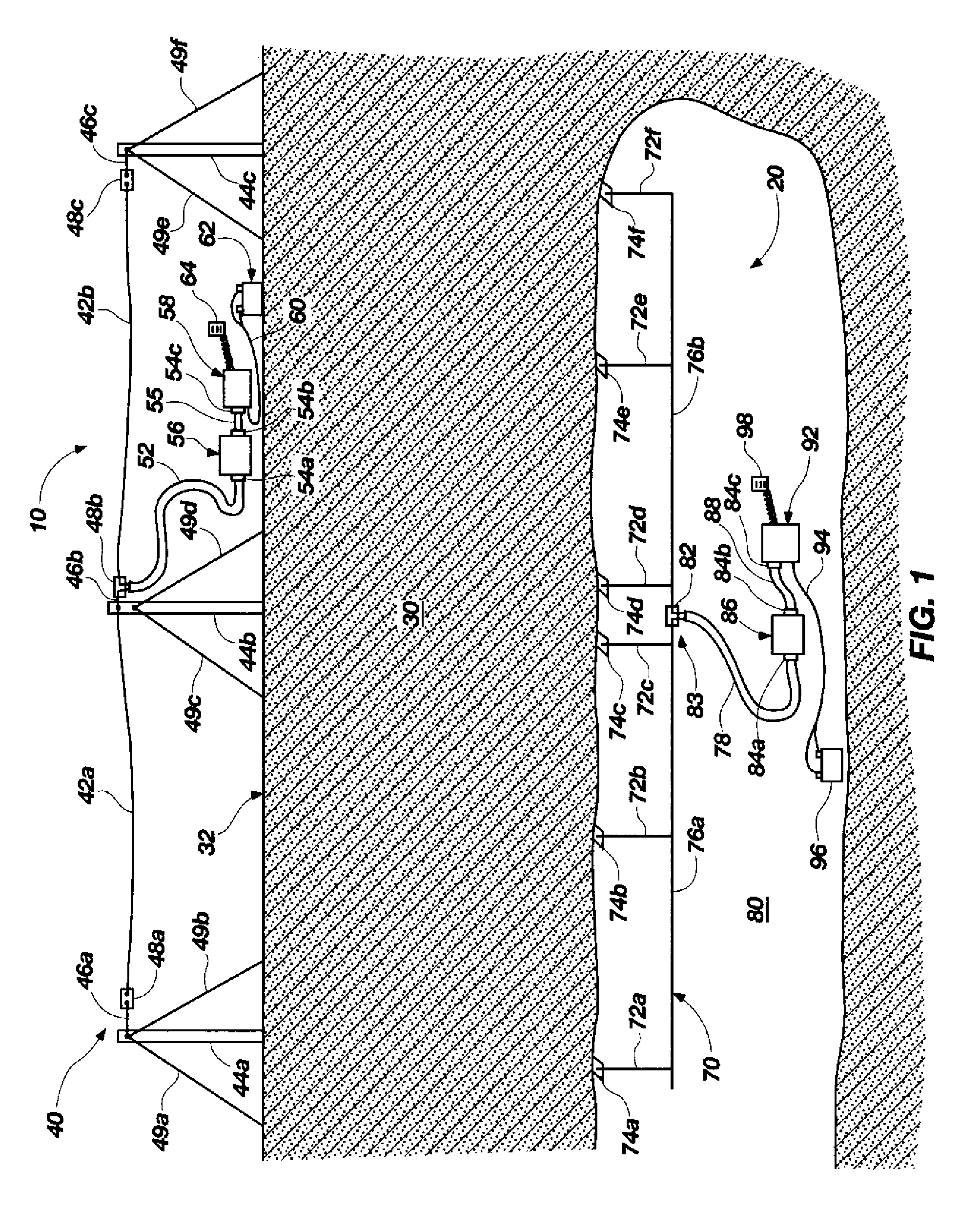
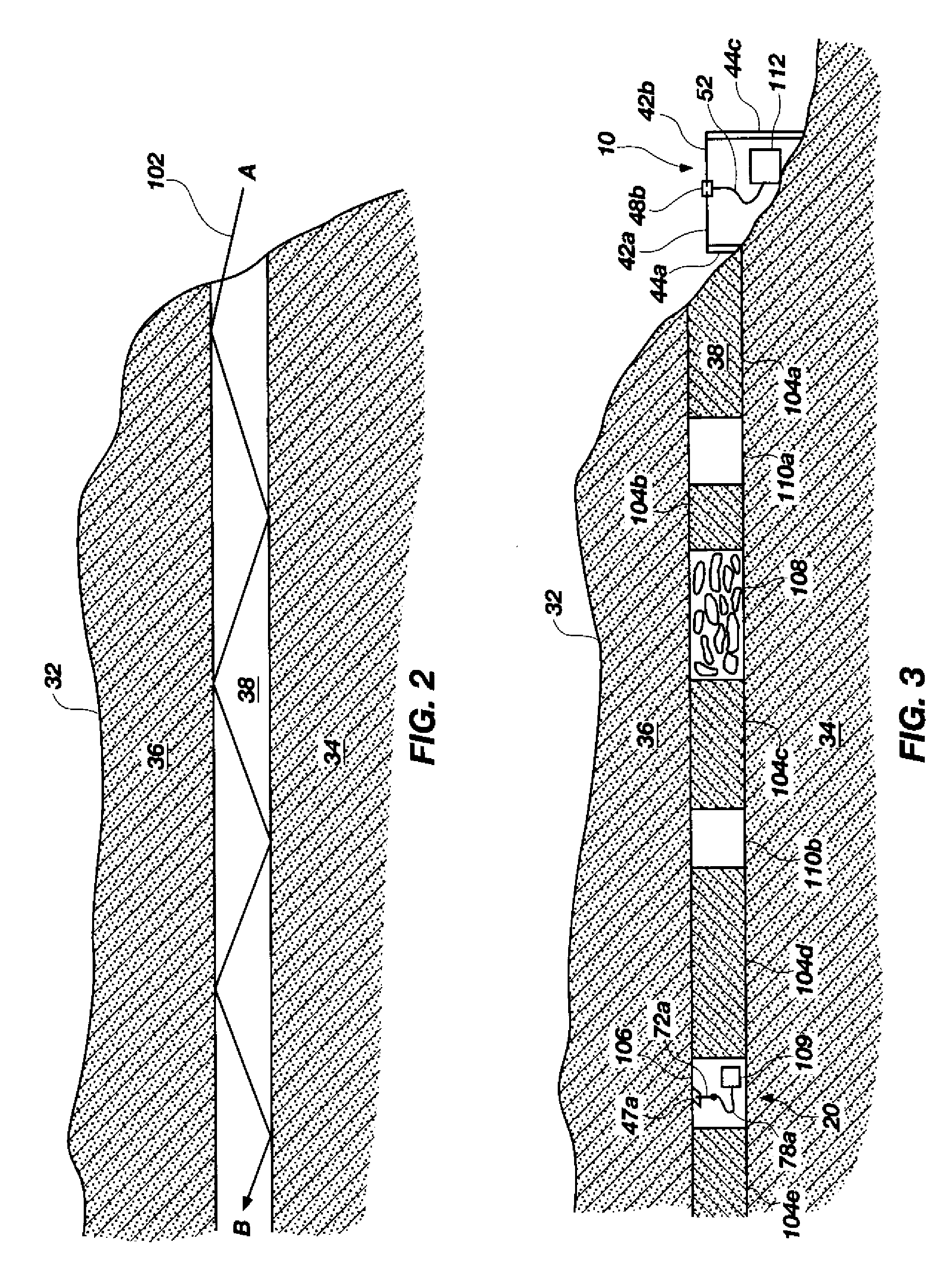
[0042]Various embodiments of the invention are now described with reference to the Figures, where like reference numbers indicate identical or functionally similar elements. The embodiments of the present invention, as generally described and illustrated in the Figures herein, could be arranged and designed in a wide variety of different configurations. Thus, the following more detailed description of several exemplary embodiments of the present invention, as represented in the Figures, is not intended to limit the scope of the invention, as claimed, but is merely representative of the embodiments of the invention.

DEFINITIONS AND TERMINOLOGY

[0043]The word “exemplary” is used exclusively herein to mean “serving as an example, instance, or illustration.” Any embodiment described herein as “exemplary” is not necessarily to be construed as preferred or advantageous over other embodiments. While the various aspects of the embodiments are presented in drawings, the drawings are not necess...


PUM


Abstract

Systems and methods for wirelessly sending signals through the earth between transmitting and receiving antennas are disclosed, wherein the communicating antennas are of the types that generate significant far field radiation and may interact substantially through the emission and absorption of electromagnetic radiation in addition to magnetic coupling. Frequencies are typically chosen which may be much higher than those conventionally used for through-the-earth (TTE) communications. In many situations where TTE communication is desired, the electromagnetic coupling and associated magnetic coupling produced and utilized by these certain types of antennas provide greater effective communications ranges when compared with the ranges that are obtainable with antennas interacting predominately by magnetic coupling alone.

Description

CROSS-REFERENCE TO RELATED APPLICATION[0001]This application claims the benefit of priority under 35 U.S.C. §119(e)(1) to U.S. Provisional Patent Application 61 / 183,893, filed Jun. 3, 2009, the disclosure of which hereby incorporated herein, in its entirety, by this reference.TECHNICAL FIELD[0002]The present invention relates generally to techniques and systems for communicating wirelessly through earth formations and, more specifically, to the use of radiating antennas to wirelessly communication through earth formations.BACKGROUND OF RELATED ART[0003]Wireless communication through the earth has been pursued vigorously over the last century. Applications would include the rescue of trapped miners, improved efficiency in mining operations, and improved telemetry from underground facilities, such as boreholes used in underground geological measurements. Yet, the prior art has not reached the point of providing two-way communication through the earth to mines or tunnels of any useful ...

Claims


Application Information

Patent Timeline
Patent Type & Authority Applications(United States)
IPC IPC(8): H04B13/02H01Q1/50
CPCH04B13/02
Inventor MARSHALL, DAVID L.
Owner MARSHALL RADIO TELEMETRY
Why Eureka
Try Eureka