Blood dialysis apparatus

a technology of hemodialysis and apparatus, which is applied in the direction of suction devices, control devices, other medical devices, etc., can solve the problems of air trapped in the mesh and the risk of air entrainment into the patient's body

Inactive Publication Date: 2010-12-09
JMS CO LTD +1
View PDF1 Cites 18 Cited by
  • Summary
  • Abstract
  • Description
  • Claims
  • Application Information

AI Technical Summary

Benefits of technology

[0026](1) According to the hemodialysis apparatus including the control means G1 according to the present invention, as the first process as illustrated in FIGS. 7 to 9; the dialysate that has been pushed into the hollow fiber within the hemodialyzer D through the reverse filtering operation due to the third fluid feeding means P3 is allowed to flow in the first flow passage extending from the connection portion between the hemodialyzer D and the artery side blood line L3 to the vein side chamber CV through the joint portion in the loop formed by connecting the artery side blood line L3 and the vein side blood line L4 in the stated direction, to thereby prime the flow passage and the hemodialyzer D.
[0027]In this example, because the air within the first flow passage passes through the mesh disposed in the vein side chamber CV earlier than the dialysate, the air is not trapped in the mesh.
[0028]Then, as illustrated in FIGS. 10 and 11, as the second process, the dialysate is allowed to flow in the second passage extending from the connection portion between the hemodialyzer D and the vein side blood line L4 to the vein side chamber CV, which is the remaining flow passage of the loop, in the stated direction, to thereby prime the flow passage and the hemodialyzer D.
[0029]As illustrated in FIG. 10, the air within the second passage flows into the vein side chamber CV earlier than the dialysate. However, the air that flows into the vein side chamber CV does not reach the mesh disposed in the vein side chamb

Problems solved by technology

Therefore, there arises a problem in that the air is trapped in the mesh as illustrated in FIG. 4, and remains in the extracorporeal circulation circuit as illustrated in FIGS. 5 and 6.
If the air remains in the extracorpor

Method used


Image

  • Blood dialysis apparatus
  • Blood dialysis apparatus
  • Blood dialysis apparatus

Examples


first embodiment

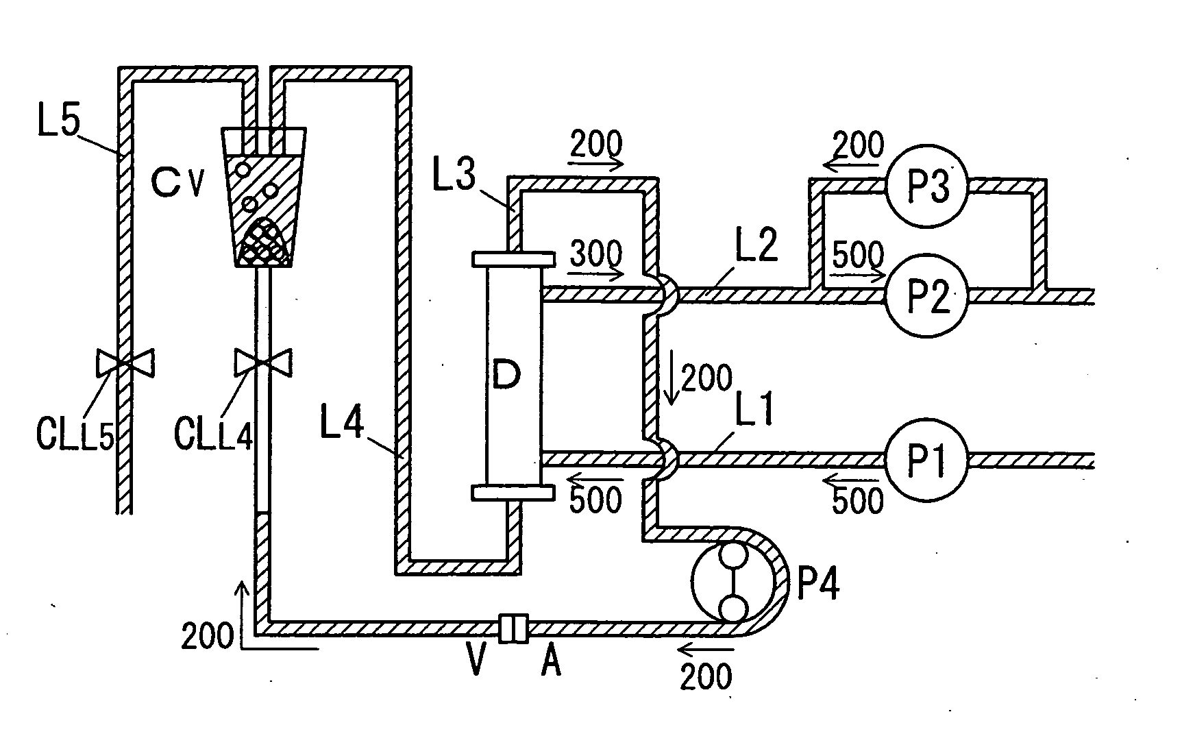
[0070]The first embodiment is a hemodialysis apparatus including a hemodialyzer D of a wet type.

[0071]FIGS. 7 to 11 are diagrams illustrating the operation of the first embodiment, and flows of a dialysate and air due to the operation. Numerical values illustrated in the figures indicate flow rates of the dialysate, and arrows indicate directions along which the dialysate flows.

[0072]The first embodiment is characterized in flow passage selection and a washing direction of the priming solution (dialysate) due to control means G1, which is described.

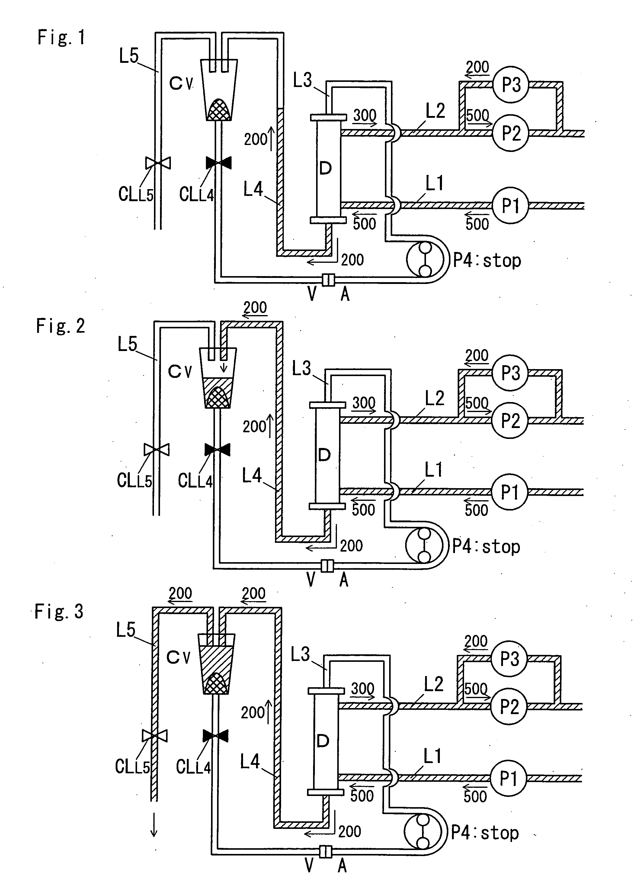
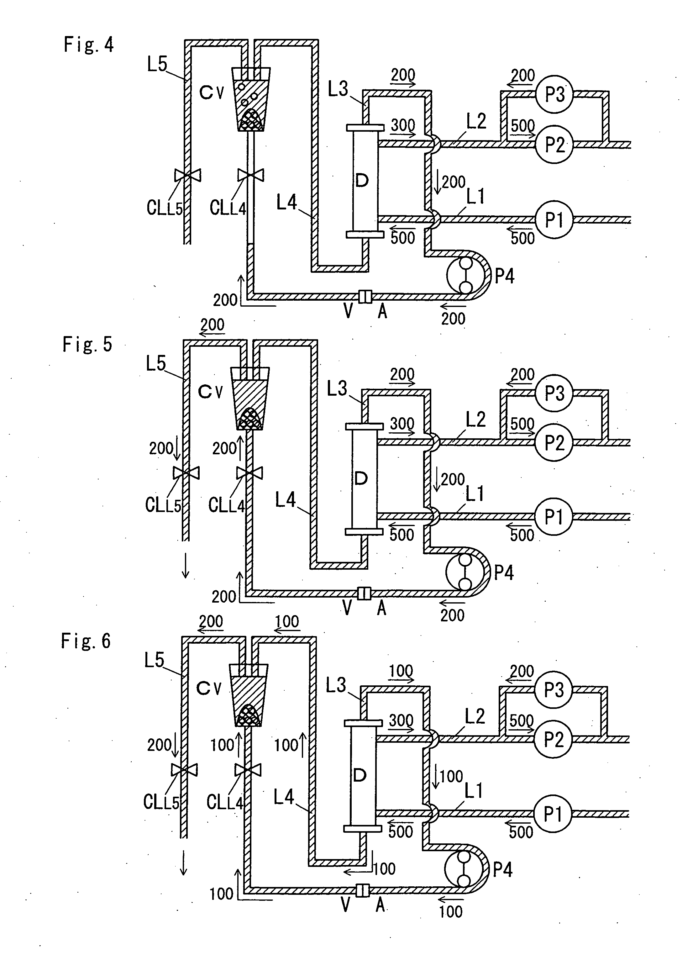
[0073](First Process)

[0074]In a first process, as illustrated in FIG. 7, a blood pump P4 reversely rotates at the same speed as a reverse filtration speed made by third fluid feeding means P3. For example, in a state where each of first fluid feeding means P1 and second fluid feeding means P2 is operated at a flow rate of 500 ml / min, the third fluid feeding means P3 is operated at 200 ml / min in the reverse filtration direction, and the bl...

second embodiment

[0095]The second embodiment is a hemodialysis apparatus including a hemodialyzer D of the wet type or the dry type.

[0096]FIGS. 12 to 17 are diagrams illustrating the operation of the second embodiment when the hemodialyzer D of the dry type is used and flows of a dialysate and the air due to the operation. Numerical values illustrated in the figures indicate flow rates of the dialysate, and arrows indicate directions along which the dialysate flows. The numerical values in the figures each indicate a flow rate of the dialysate including air when the air exists in a flow passage located at the number.

[0097]The second embodiment is also characterized in the flow selection and the washing direction of the priming solution due to the control means G2, which is described.

[0098]According to the second embodiment, as illustrated in FIGS. 12 to 17, the blood pump P4 forwardly rotates at a speed lower than the reverse filtration speed made by the third fluid feeding means P3. For example, in...


PUM


Abstract

Provided is a hemodialysis apparatus which can fundamentally solve a problem in that air is trapped in a mesh disposed in a vein side chamber during priming. A hemodialysis apparatus includes control means that conducts, in the stated order: (A) a process in which a blood pump reversely rotates at the same speed as a reverse filtration speed made by third fluid feeding means, and a dialysate flows in a flow passage extending from a connection portion between a hemodialyzer and an artery side blood line to a vein side chamber through the joint portion in a loop formed by connecting the artery side blood line and the vein side blood line, to thereby prime the flow passage and the hemodialyzer, and (B) a process in which a reverse rotation speed of the blood pump is made lower than the reverse filtration speed made by the third fluid feeding means, and the dialysate of a flow rate corresponding to a speed obtained by subtracting the reverse rotation speed of the blood pump from the reverse filtration speed made by the third fluid feeding means flows in a flow passage extending from a connection portion between the hemodialyzer and the vein side blood line to the vein side chamber, which is a remaining flow passage of the loop, to thereby prime the flow passage and the hemodialyzer.

Description

TECHNICAL FIELD[0001]The present invention relates to a hemodialysis apparatus that is used for a medical treatment with an extracorporeal circulation of blood such as hemodialysis, hemodialysis filtration, or hemofiltration, and more particularly to a hemodialysis apparatus that can fundamentally solve such a problem that air is trapped in a mesh disposed in a vein side chamber CV during priming, and then remains therein.BACKGROUND ART[0002]A hemodialysis apparatus is a type of medical equipment that extracorporeally circulates blood of a patient with renal failure or a drug intoxicated patient to perform blood purification. The hemodialysis apparatus generally includes three portions of (1) a hemodialyzer D that brings blood into contact with a dialysate through a semipermeable membrane to purify blood, (2) a dialysate supply / discharge system mainly including a dialysate supply line L1 that supplies the dialysate to the hemodialyzer D, and a dialysate discharge line L2 that discha...

Claims


Application Information

Patent Timeline
IPC IPC(8): A61M1/16A61M1/14
CPCA61M1/3643A61M1/3649A61M1/365A61M1/3465A61M1/3644A61M1/155A61M60/508
Inventor MASAOKA, KATSUNORIMAEHARA, KAZUOCHIBA, SHINGOKIM, SUNG-TEHYAMAMOTO, CHIEKO
Owner JMS CO LTD
Why Eureka
Try Eureka