

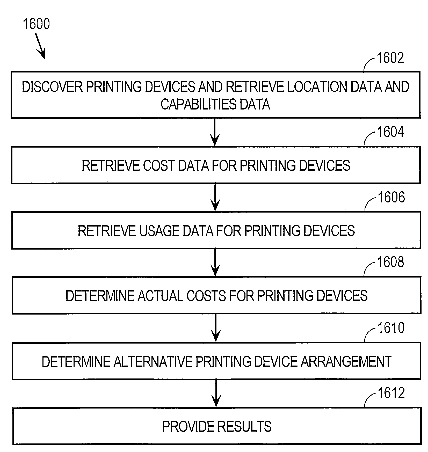
Approach For Determining Alternative Printing Device Arrangements
a printing device and arrangement technology, applied in the field of networked devices, can solve the problems of reducing power consumption, personal computers require several minutes to “boot up”, and types of equipment take a long time to power up from a powered down state, so as to reduce operating costs, reduce energy costs, and reduce costs
- Summary
- Abstract
- Description
- Claims
- Application Information
AI Technical Summary
Benefits of technology
Problems solved by technology
Method used
Image

Examples
Embodiment Construction
[0036]In the following description, for the purposes of explanation, specific details are set forth in order to provide a thorough understanding of the invention. However, it will be apparent that the invention may be practiced without these specific details. In some instances, well-known structures and devices are depicted in block diagram form in order to avoid unnecessarily obscuring the invention. Various embodiments and aspects of the invention are described hereinafter in the following sections:
[0037]I. OVERVIEW
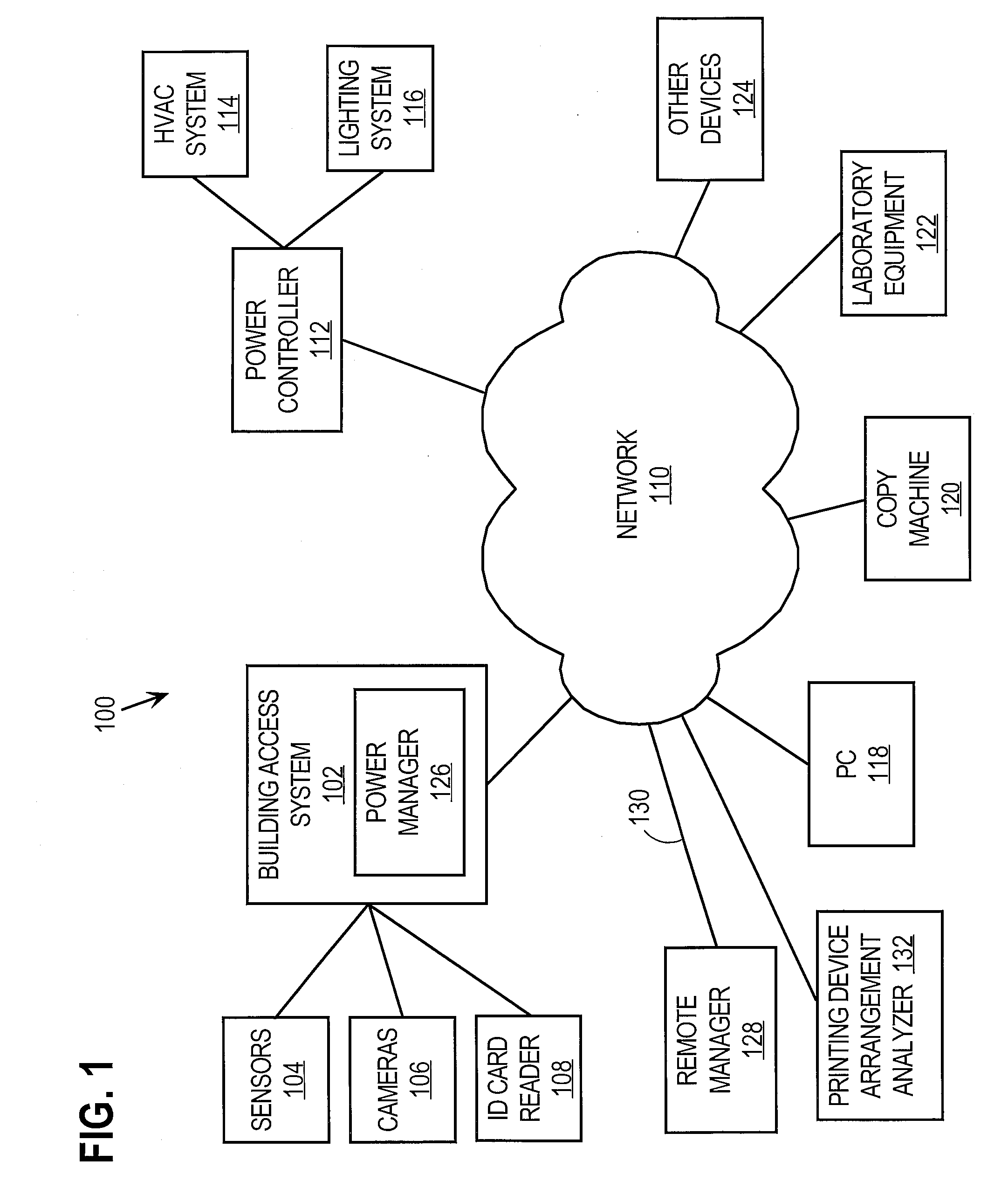
[0038]II. POWER MANAGEMENT ARCHITECTURE
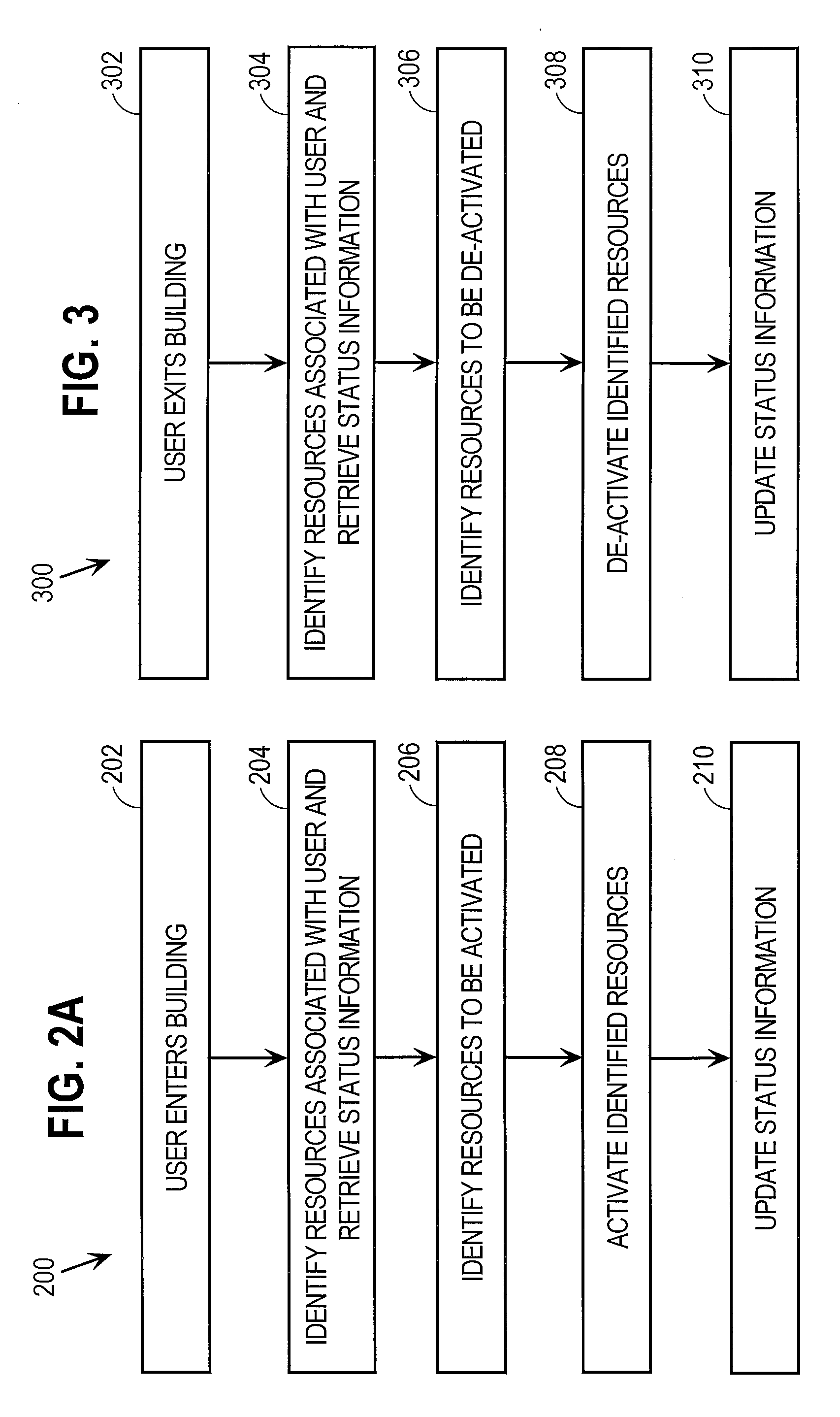
[0039]III. MANAGING POWER DURING BUILDING ENTRY AND EXIT
[0040]IV. IMPLEMENTATION MECHANISMS
[0041]V. REMOTE MANAGEMENT APPLICATIONS
[0042]VI. OPERATIONAL STATE HIERARCHIES
[0043]VII. EXAMPLE MULTI-FUNCTION PERIPHERAL (MFP) ARCHITECTURE
[0044]VIII. NETWORK DEVICE PRE-ACTIVATION[0045]A. Usage Data[0046]B. Collecting and Storing Usage Data[0047]C. Using Usage Data to Estimate Future Usage of a Network Device[0048]D. Updates to Usage Data[...
PUM
 Abstract
Description
Claims
Application Information