

Microcomputer system, microcomputer, power control method, and power control program product
- Summary
- Abstract
- Description
- Claims
- Application Information
AI Technical Summary
Benefits of technology
Problems solved by technology
Method used
Image

Examples
first exemplary embodiment
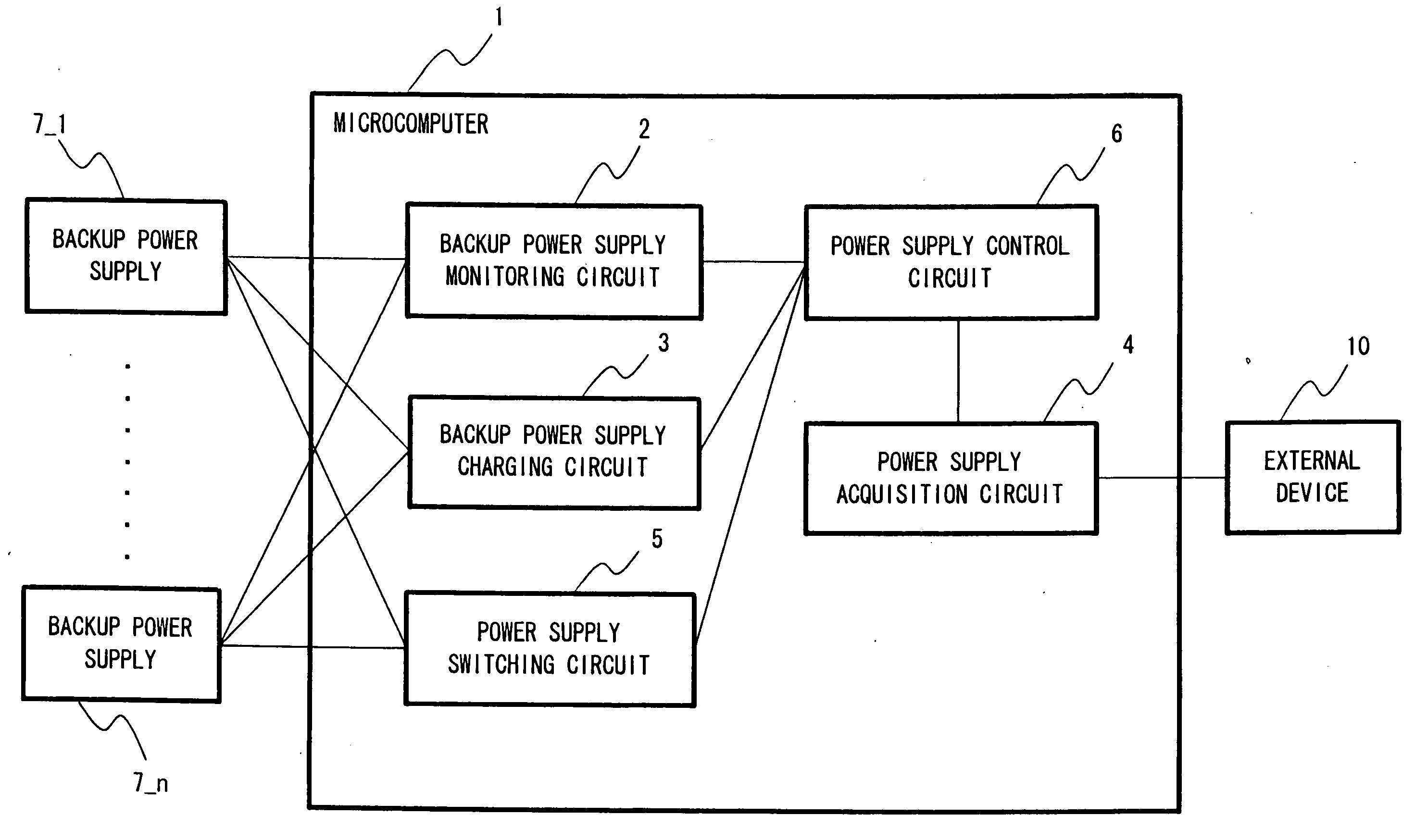
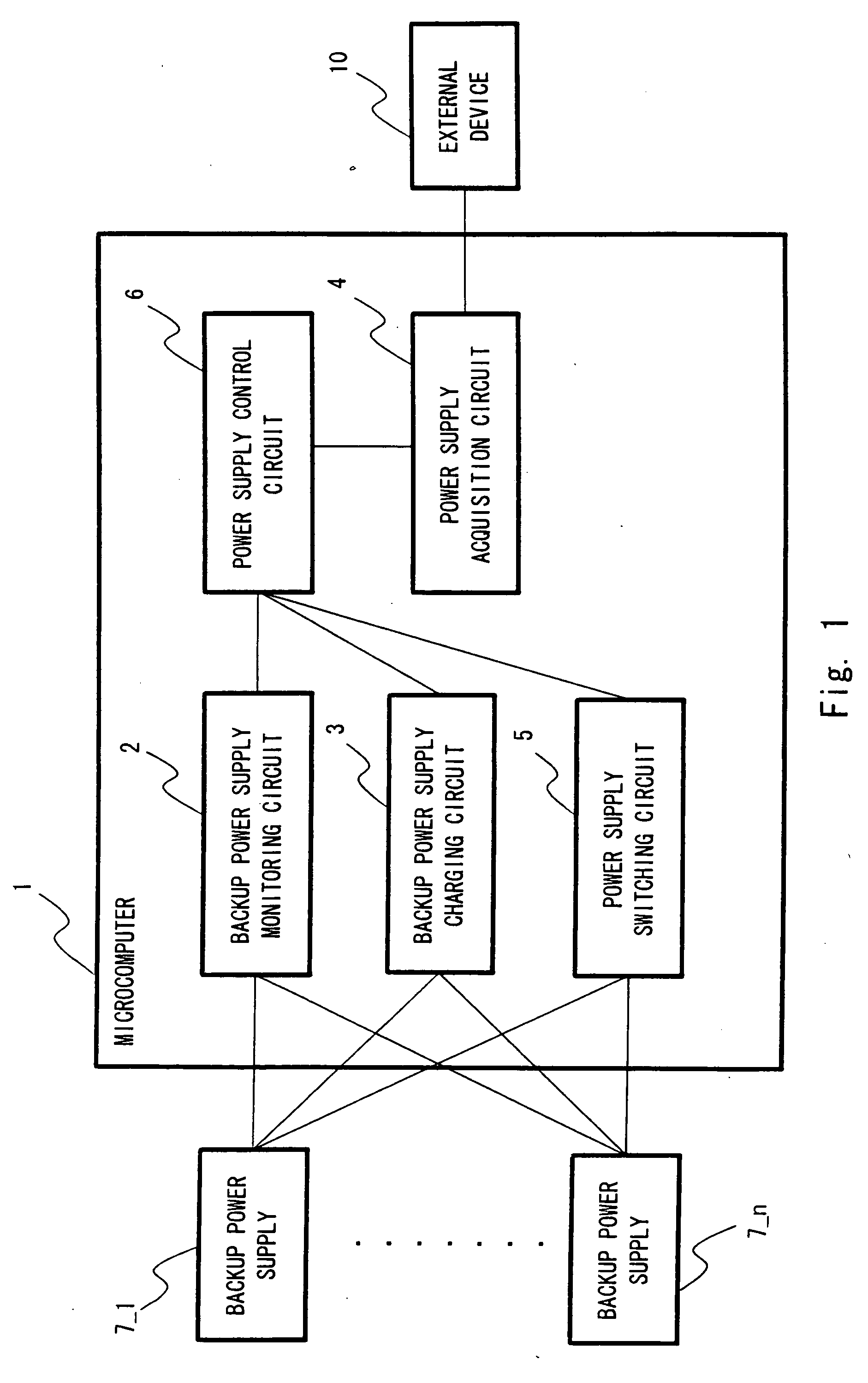
[0022]An exemplary embodiment of the invention is described with reference to the drawings. FIG. 1 illustrates the configuration of a microcomputer according to a first exemplary embodiment of the present invention.
[0023]A microcomputer 1 is provided with a backup power supply monitoring circuit 2, a backup power supply charging circuit 3, a power supply acquisition circuit 4, a power supply switching circuit 5, and a power supply control circuit 6. Further, backup power supplies 7_1 to 7—n are connected to the microcomputer 1. An external device 10 for supplying main power supply is connected to the microcomputer 1. Note that AC power supply or button cells can also supply power to the microcomputer, instead of the backup power supplies 7_1 to 7—n and the external device 10.
[0024]The backup power supply monitoring circuit 2 obtains charge amount from the backup power supplies 7_1 to 7—n. For example, the backup power supply monitoring circuit 2 is composed of an analog / digital conv...
second exemplary embodiment
[0049]Next, a configuration example of a microcomputer according to a second exemplary embodiment of the present invention is described with reference to FIG. 6. The microcomputer according to the second exemplary embodiment of the present invention is provided with a USB power supply circuit 8. Other configuration is the same as FIG. 1, thus the explanation is omitted.
[0050]The USB power supply circuit 8 supplies the main power supply obtained by the power supply acquisition circuit 4 to a USB device 11, which is connected to the USB power supply circuit 8. Specifically, the USB power supply circuit 8 supplies USB bus power supply to the USB device 11, which is connected to the USB power supply circuit 8. The USB device 11 supplied with the USB bus power operates with the USB bus power supply as the main power supply.
[0051]Next, the process flow of the power supply to the external device 10 according to the second exemplary embodiment of the present invention is described with refe...
third exemplary embodiment
[0054]Next, the process flow of the power supply switch of a microcomputer according to a third exemplary embodiment of the present invention is described with reference to FIG. 8. The configuration of the microcomputer is the same as that of FIG. 1.
[0055]First, the power supply acquisition circuit 4 detects that the power supply from the external device 10 is off (S41). At this time, the cause that the power supply from the external device 10 is turned off may be either of the abovementioned first or the second cause.
[0056]Next, the power supply control circuit 6 obtains the state of the charge amount of the backup power supplies 7_1 to 7—n from the backup power supply monitoring circuit 2 (S42).
[0057]Next, the power supply control circuit 6 checks a necessary voltage level until the microcomputer currently operating completes the operation. The necessary voltage level may be notified to the power supply control circuit 6 from a CPU of the microcomputer. Or the power supply control...
PUM
 Abstract
Description
Claims
Application Information