Seat-Air Conditioning System for Automotive Vehicles

Active Publication Date: 2010-12-16
HANON SYST
View PDF4 Cites 32 Cited by
  • Summary
  • Abstract
  • Description
  • Claims
  • Application Information

AI Technical Summary

Benefits of technology

[0030]In the seat air-conditioning system of the present invention, the cold air or the hot air is directly fed to the driver seat and the front passenger seat, which makes it possible to supply the c

Problems solved by technology

However, the conventional seat air-conditioning system set forth above suffers from shortage in the flow rate of the cold air or the hot air, because it makes use of a part of the cold air or the hot air drawn from the console duct 1a.
This leads to a reduction in the capability of cooling or heating the seat portions 5a and 7a.
Since the auxiliary blower 3b is integrally mounted to the air-conditioning unit 3, the above-cited conventional technique poses a problem in that the air-conditioning unit 3 becomes structurally complicated, costly to manufacture and difficult to fabricate.
This results in a highly complicated configuration and requires doing a difficult task when assembling different parts together.
Inasmuch as the auxiliary blower 3b is integrally mou

Method used


Image

  • Seat-Air Conditioning System for Automotive Vehicles
  • Seat-Air Conditioning System for Automotive Vehicles
  • Seat-Air Conditioning System for Automotive Vehicles

Examples


first embodiment

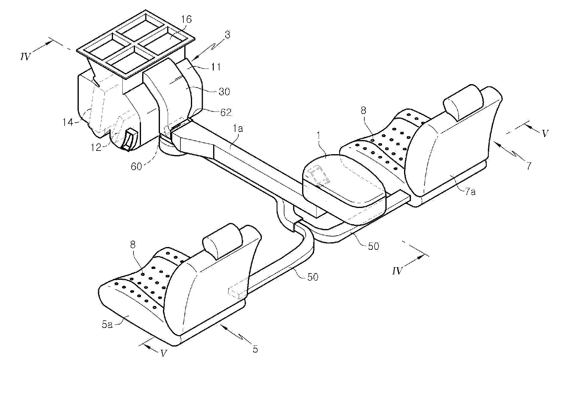
[0044]FIG. 3 is a bottom perspective view showing a characterizing part of an air conditioning system for automotive vehicles in accordance with the present invention. FIG. 4 is a section view taken along line IV-IV in FIG. 3.

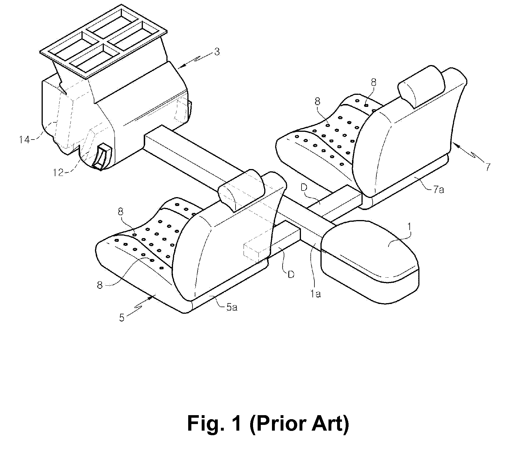
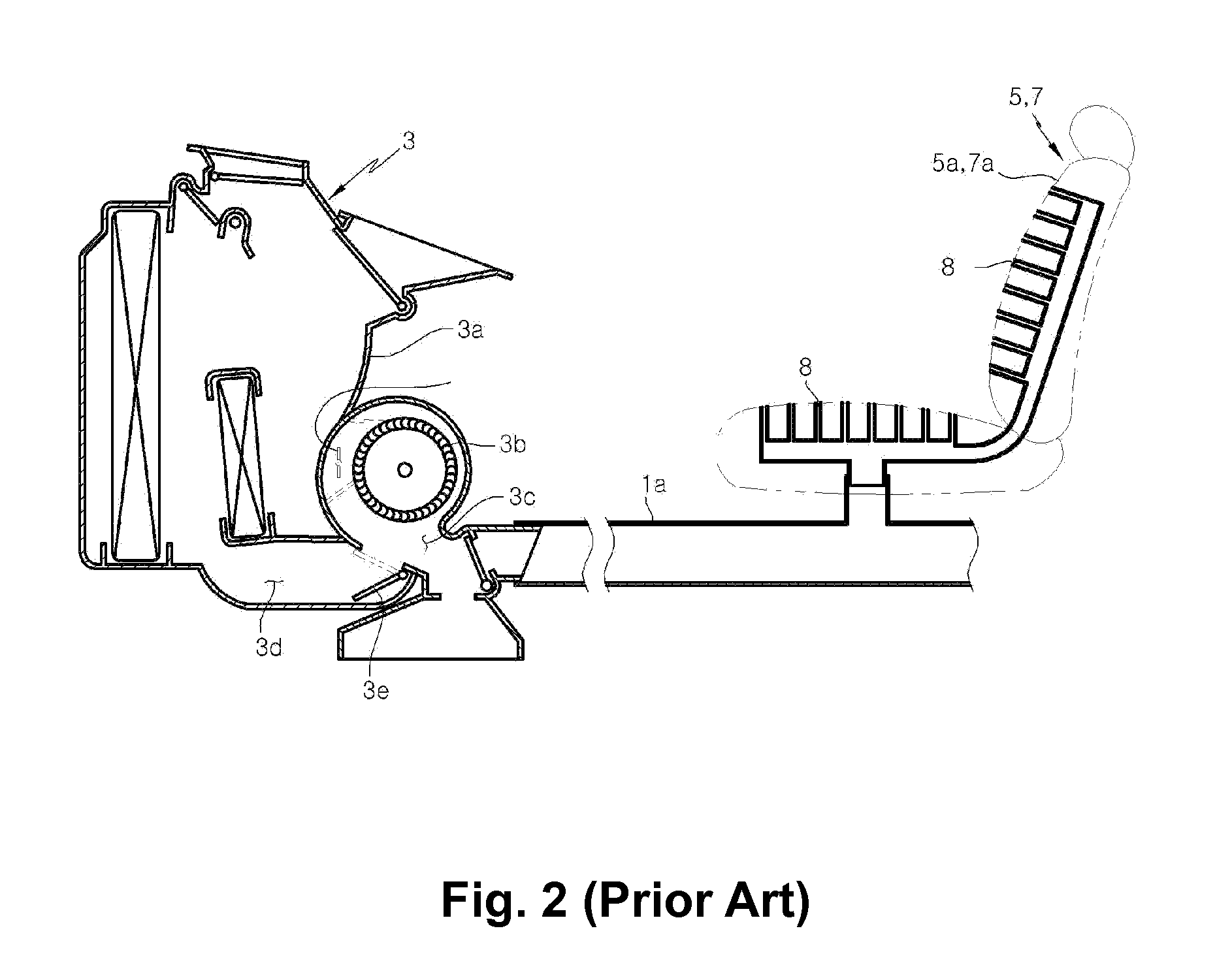
[0045]Prior to describing the seat air-conditioning system of the present invention, brief description will be made on the general aspect of a vehicle air-conditioning system with reference to FIGS. 3 through 5.

[0046]The vehicle air-conditioning system includes an air-conditioning unit 3 provided with an air-conditioning case 11. The air-conditioning case 11 has an internal passage 11a. A heater core 12 and an evaporator 14 are installed within the internal passage 11a.

[0047]The heater core 12 serves to generate a hot air by heating the air present within the internal passage 11a of the air-conditioning case 11. The evaporator 14 functions to generate a cold air by cooling the air present within the internal passage 11a of the air-conditioning case 11.

[0048]Th...

second embodiment

[0075]Referring to FIG. 7, there is shown a seat air-conditioning system in accordance with a second embodiment of the present invention.

[0076]The seat air-conditioning system of the second embodiment includes an outlet duct 30 through which to draw the cold air or the hot air from the air-conditioning case 11. The second outlet mouth 36 of the outlet duct 30 is closed in this seat air-conditioning system. This makes it possible to omit the seat blower 70 otherwise mounted to the second outlet mouth 36. The outlet duct 30 having the closed second outlet mouth 36 is used in an air-conditioning system in which the cold air or the hot air need not be discharged through the second outlet mouth 36, namely an air-conditioning system having no seat cooling or heating performance.

[0077]According to the second embodiment, an air-conditioning system having no seat cooling or heating function can be manufactured by merely using the outlet duct 30 with the closed second outlet mouth 36. This me...

third embodiment

[0080]Referring to FIGS. 8 and 9, there is shown a seat air-conditioning system in accordance with a third embodiment of the present invention.

[0081]In the seat air-conditioning system of the third embodiment, the second outlet mouth 36 is formed in the upper portion of the outlet duct 30, the seat blower 70 being mounted to the second outlet mouth 36. Forming the second outlet mouth 36 in the upper portion of the outlet duct 30 makes it possible to arrange the seat blower 70 in the wide space above the air-conditioning case 11.

[0082]As compared with the seat air-conditioning system of the first embodiment in which the seat blower 70 is arranged in the narrow space below the air-conditioning case 11, it is easy and convenient to attach and remove the seat blower 70. This helps increase the degree of freedom of design and enhance the ease of repair and maintenance.

[0083]It is preferred that the seat blower 70 is mounted to the upper surface portion of the air-conditioning case 11 to ...


PUM


Abstract

A seat air-conditioning system for automotive vehicles includes an air-conditioning unit for generating cold air or hot air, a driver seat including a seat portion provided with a plurality of air discharge holes through which to discharge the cold air or the hot air to the outside, a front passenger seat including a seat portion provided with a plurality of air discharge holes through which to discharge the cold air or the hot air to the outside, an outlet duct mounted to the air-conditioning unit for drawing the cold air or the hot air from the air-conditioning unit therethrough, a seat duct connected to the outlet duct for supplying the cold air or the hot air to the driver seat and the front passenger seat therethrough, and a seat blower attached to the outlet duct for blowing the cold air or the hot air at an increased flow rate.

Description

FIELD OF THE DISCLOSURE[0001]The present invention relates to a seat air conditioning system for automotive vehicles and, more particularly, to a seat air-conditioning system for automotive vehicles capable of improving the cooling or heating performance for a driver seat and a front passenger seat.BACKGROUND OF THE DISCLOSURE[0002]Recently available air-conditioning systems for automotive vehicles are provided with various kinds of convenience devices for enhancing the pleasantness within a vehicle room. For example, there are known a console air-conditioning system for cooling or heating a console box and a seat air-conditioning system for cooling or heating a driver seat and a front passenger seat.[0003]As shown in FIG. 1, the console air-conditioning system is configured to supply a cold air or a hot air generated in an air-conditioning unit 3 to a console box 1. This makes it possible for the console box 1 to serve as a refrigerator or a heating cabinet.[0004]The seat air-condi...

Claims


Application Information

Patent Timeline
IPC IPC(8): F25B29/00F24F7/007F25D31/00
CPCB60H1/00285B60H2001/003B60N2/5628B60N2/5657Y10S454/907
Inventor LEE, DAE WOONGKIM, JONG SUJIN, SOO-YONG
Owner HANON SYST
Why Eureka
Try Eureka