Flow diverter for drilling

Inactive Publication Date: 2010-12-16
SCHLUMBERGER TECH CORP
View PDF5 Cites 13 Cited by
  • Summary
  • Abstract
  • Description
  • Claims
  • Application Information

AI Technical Summary

Benefits of technology

[0009]The side flow channels of the flow diverter can be arranged to divert flow that has come from inside the drilling system to the annulus above the point at which the side channels divert fl

Problems solved by technology

However the use of coiled tubing drilling is still limited due to: the small portion of the global CT rig fleet capable of handling the large tubing size needed for drilling, the size and weight of a typical spool of coiled pipe is not always compatible with the hosting capacity o

Method used


Image

  • Flow diverter for drilling
  • Flow diverter for drilling
  • Flow diverter for drilling

Examples


Embodiment Construction

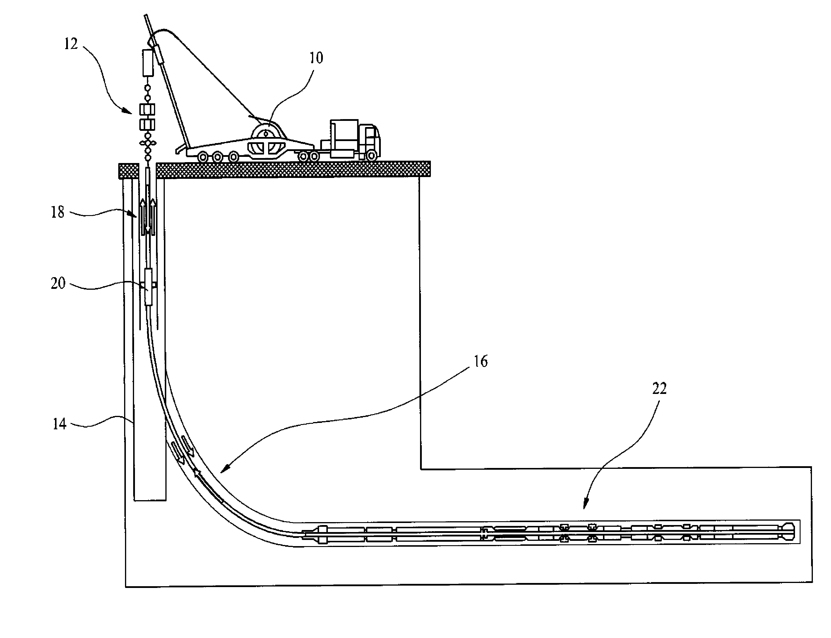
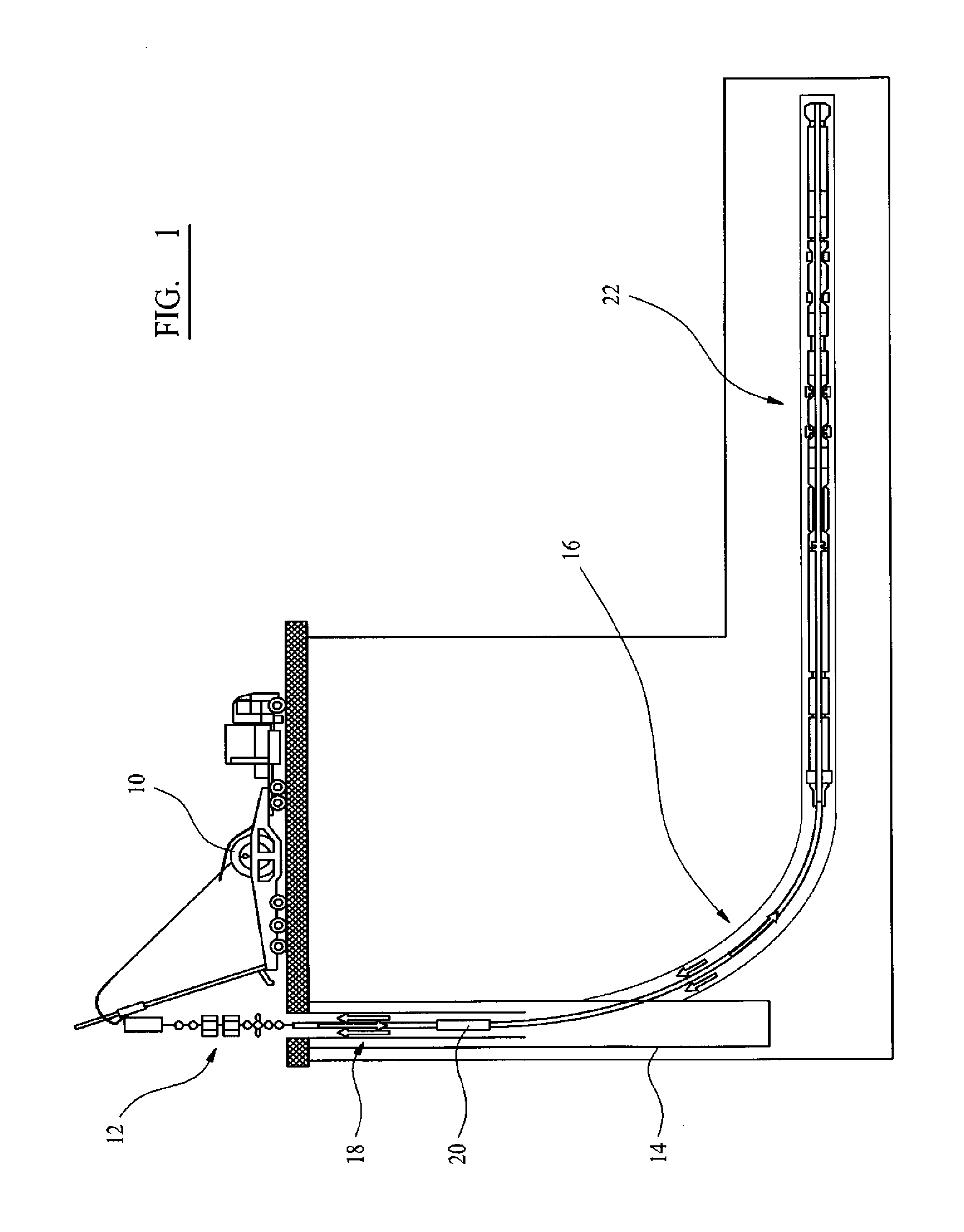
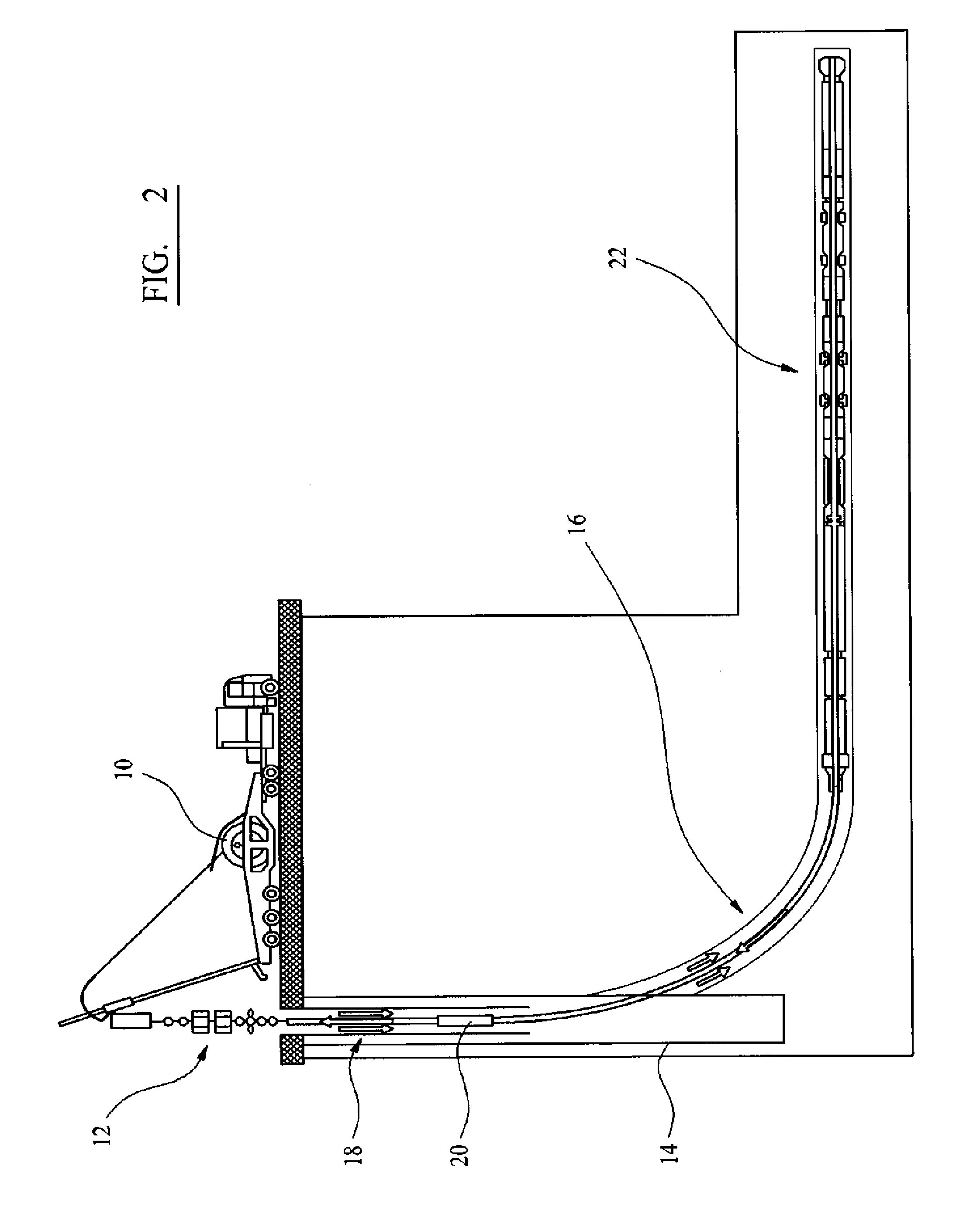
[0030]With reference to FIG. 1 a drilling operation is conducted using a conventional coiled tubing unit 10 and injector / pressure control setup 12 at the surface of the well 14 and is being used to drill a lateral well 16 extending away from the main well 14. The drilling apparatus comprises a coiled tubing conveyance system 18, a diverter 20 and a drilling system 22. The diverter 20 is adjustable to control the path through which the fluid can flow through the coiled tubing depending on the drilling conditions. The diverter is positioned in the main well 14, such that when the diverter is configured to direct fluid into the annulus the fluid will be released into a cased portion of the well.

[0031]As shown in FIG. 1 the coiled tubing conveyance system 18 can carry fluid from the surface to the section of the well being drilled. The fluid passes directly through the diverter 20 from the upper region of the CT conveyance system 18 above the diverter to the lower region of the CT conve...


PUM


Abstract

An apparatus for drilling a borehole in a well is provided. The apparatus comprises a tubular conveyance system; a drilling system connected to one end of the tubular conveyance system and comprising a bottom hole assembly; and a flow diverter positioned in the tubular conveyance system and comprising a first flow channel configured to receive fluid from inside the conveyance system and at least two side flow channels configured to direct fluid from the first flow channel out of the tubular conveyance system. The fluid flow between the first flow channel and each side flow channels is controlled by a valve which is operable to divert fluid out of the tubular conveyance system or to maintain the fluid in the tubular conveyance system.

Description

CROSS-REFERENCE TO RELATED APPLICATIONS[0001]The present application is based on and claims priority to GB Application No. 0722882.8, filed 22 Nov. 2007; and International Patent Application No. PCT / EP2008 / 009809, filed 19 Nov. 2008. The entire contents of each are herein incorporated by reference.TECHNICAL FIELD [0002]This invention relates to methods and apparatus for drilling boreholes, in particular to drilling with a coiled tubing system.BACKGROUND ART [0003]Drilling using coiled tubing has been going on for many years and hundreds of wells are now drilled every year with this technology. Coiled tubing drilling (CTD) comprises drilling with a continuous pipe coiled onto a reel with a downhole drilling motor typically providing rotation to the drill bit. The tubing is conveyed into a borehole with a special injector system mounted on the surface. Coiled tubing drilling shows many advantages compared to conventional drilling with jointed pipes, including: ability to operate in pr...

Claims


Application Information

Patent Timeline
IPC IPC(8): E21B21/10E21B34/06E21B7/00E21B21/12
CPCE21B7/068E21B21/12E21B21/103E21B17/203E21B34/00E21B43/123
Inventor DENOIX, HENRIDEIBLE, CHARLES
Owner SCHLUMBERGER TECH CORP
Why Eureka
Try Eureka