Tool for transferring controlled amounts of fluid into and from a fluid flow circuit

a fluid flow circuit and fluid flow technology, applied in liquid handling, tomography, packaging goods types, etc., can solve the problems of cooling liquid leaked through one or more of the couplers, significant amount of cooling liquid still lost or inadvertently leaked from the fluid flow circuit, and x-ray tube hotness, so as to facilitate visual determining the amount of fluid, including liquid and any trapped air, within the tube.

Inactive Publication Date: 2007-03-29
GENERAL ELECTRIC CO
View PDF13 Cites 12 Cited by
  • Summary
  • Abstract
  • Description
  • Claims
  • Application Information

AI Technical Summary

Problems solved by technology

During such operation of the CT scanner, the x-ray tube is generally supplied with large amounts of electrical power that are converted into heat, which thereby causes the x-ray tube to get hot.
Despite being interconnected in the above-described manner, sometimes a significant amount of cooling liquid is still lost or inadvertently leaked from the fluid flow circuit when servicing one or more of the above-mentioned circuit components.
In particular, though the circuit's couplers are typically equipped with automatic shut-off valves, cooling liquid is nevertheless often leaked via one or more of these couplers as they are disconnected and re-connected during service.
If such a loss of cooling liquid is not properly corrected, the fluid flow circuit may suffer a corresponding reduction in its overall cooling capability.
As a result, overheating and burnout of the x-ray tube as well as nearby electrical components may occur.
Thus, when adding cooling liquid to the fluid flow circuit, care must be exercised so as to not add too much liquid and exceed this predetermined limit level, for the expandable bladder of the accumulator may consequently rupture or burst during subsequent operation when the liquid is hot and expanded, thereby potentially causing the spillage of hot oil from the CT scanner.
Having to newly introduce or add such a controlled amount of cooling liquid into the fluid flow circuit, however, is often a laborious and undesirably time-consuming task.
Furthermore, since fluid spills while carrying out such a liquid replenishment process are not uncommon, the process is oftentimes rather messy as well.
In addition to sometimes losing cooling liquid, sometimes a significant amount of air is inadvertently introduced into the fluid flow circuit when servicing one or more of the above-mentioned circuit components.
If such ingestion of air into the fluid flow circuit is not properly corrected, certain consequences may occur.
For example, with the introduction of air into the fluid flow circuit, hot pockets of air are apt to develop and be circulated through the circuit during operation, thereby reducing the circuit's overall cooling capability.
As a result, highly localized heating and burnout of the x-ray tube as well as nearby electrical components may occur.
In addition, artifacts may begin to appear in CT scanner images, thereby reducing scanner image resolution and quality.
Furthermore, with air pockets circulating through the fluid flow circuit, the centrifugal pump is likely to begin “choking” and operating less efficiently, and may even incur damage due to cavitation.
Such methods proposed to date, however, typically involve numerous steps and are characteristically labor intensive.
Consequently, the methods are often rather time-consuming and highly inefficient overall.
Furthermore, since fluid spills when implementing such methods are not uncommon, the methods are frequently quite messy as well.

Method used


Image

  • Tool for transferring controlled amounts of fluid into and from a fluid flow circuit
  • Tool for transferring controlled amounts of fluid into and from a fluid flow circuit
  • Tool for transferring controlled amounts of fluid into and from a fluid flow circuit

Examples


Embodiment Construction

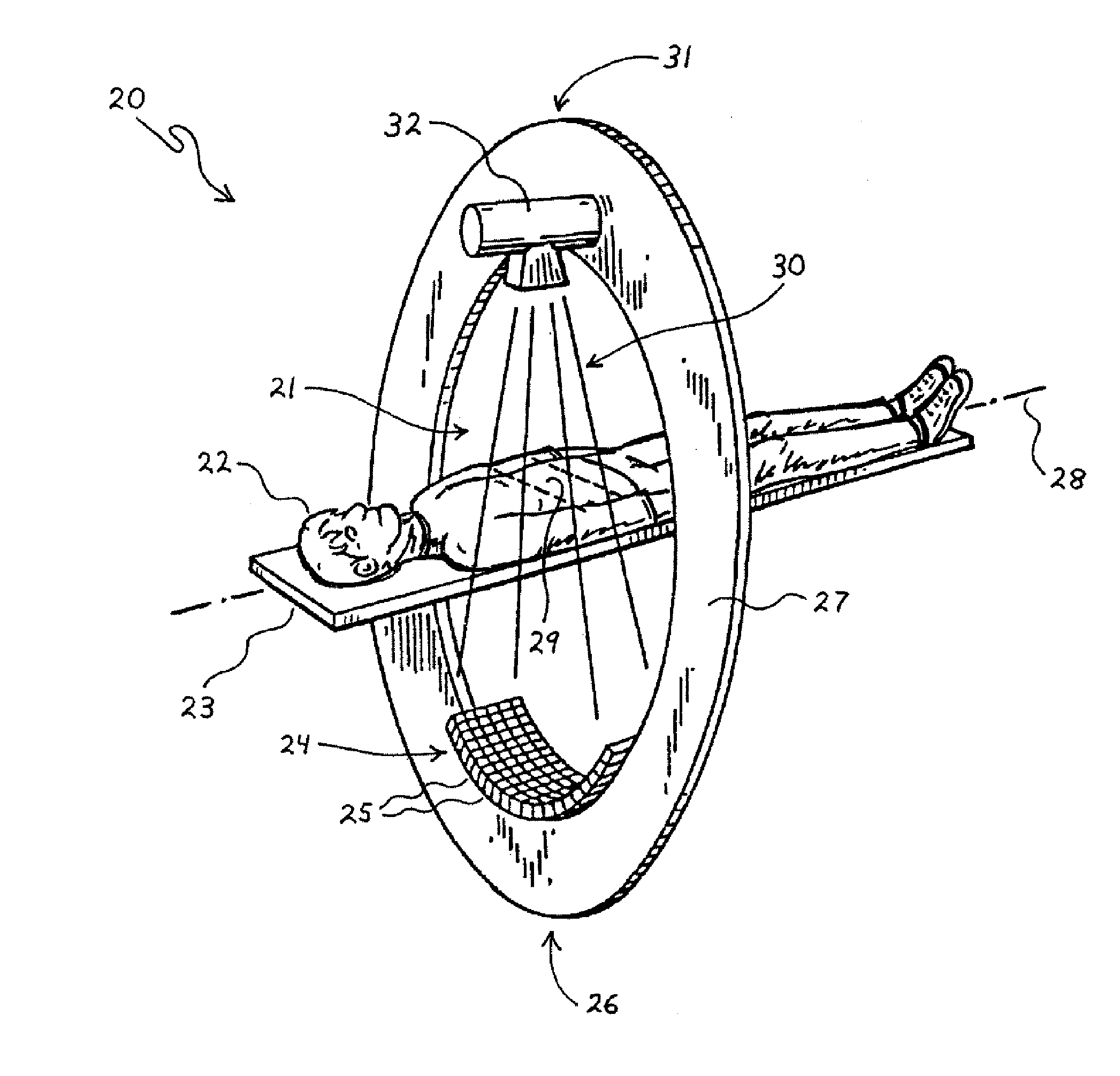
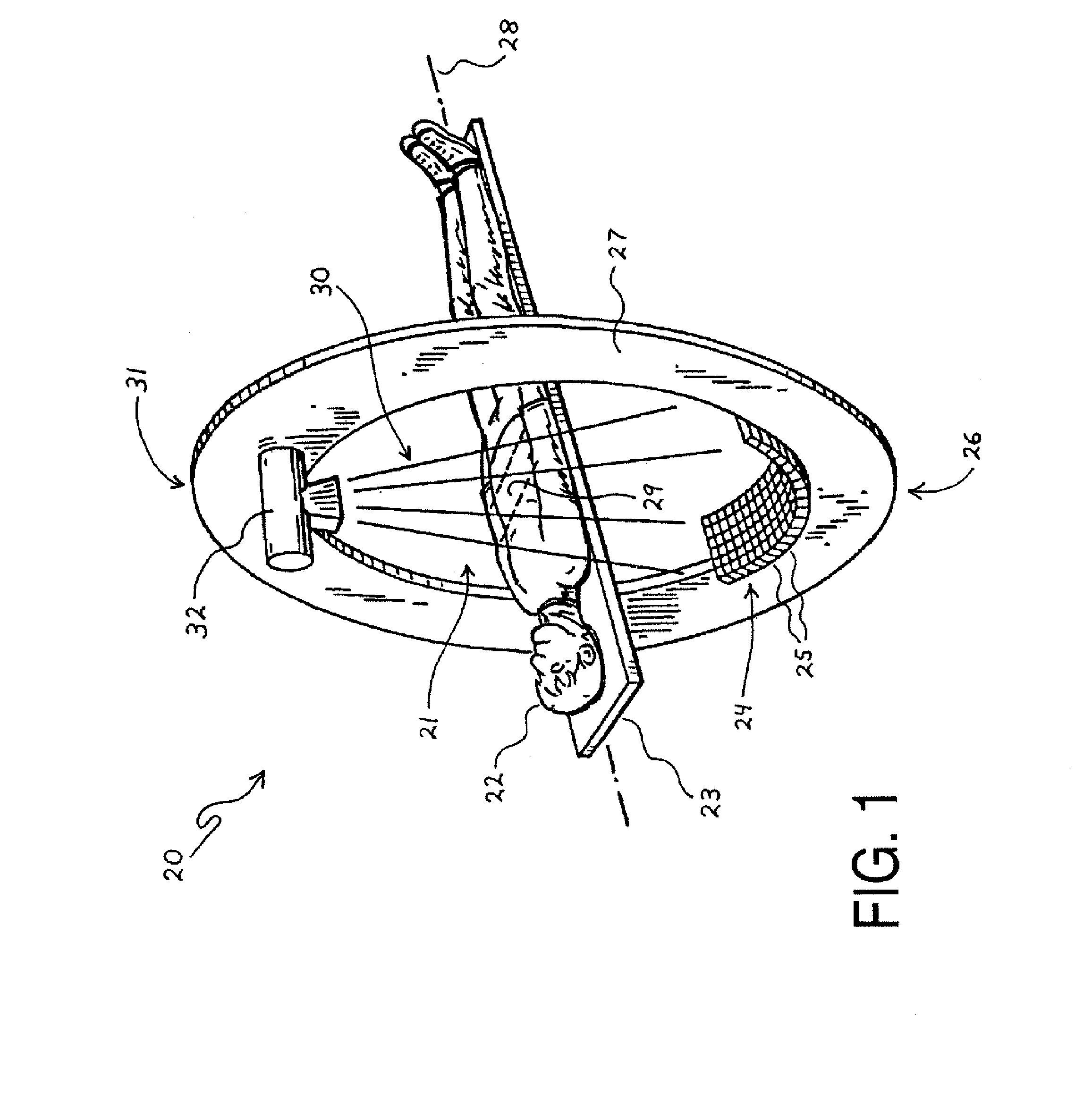
[0063]FIG. 1 is a perspective view highlighting some of the primary scanning elements in a largely conventional computed tomography (CT) imaging system 20. As shown, the CT imaging system 20 includes an elongated patient table 23, an annular gantry 27, an x-ray tube 32, and an arcuate detector 24. In general, the patient table 23 is situated within an aperture or opening 21 defined within the gantry 27 so as to be collinearly aligned with an axis 28 defined through the center of the gantry's opening 21. The x-ray tube 32 is mounted at or near a 12 o'clock position 31 on the gantry 27, and the detector 24 is mounted at or near a 6 o'clock position 26 on the gantry 27.

[0064] For operation of the CT imaging system 20, a subject or patient 22 is laid upon the patient table 23, and the table 23 is moved along the gantry axis 28 by an electric motor (not shown) so as to position a particular anatomical section or region of interest (ROI) 29 within the patient 22 underneath the x-ray tube...


PUM

PropertyMeasurementUnit
lengthaaaaaaaaaa
shapeaaaaaaaaaa
translucentaaaaaaaaaa

Abstract

A tool for transferring controlled amounts of fluid into and from a fluid flow circuit is disclosed herein. The tool includes a substantially closed tube having a first end, a second end, and a chamber therein; an elongate plunger having a fore end extending inside the chamber and toward the second end of the tube, an aft end extending outside the chamber and from the first end of the tube, a piston-like structure on the fore end, and a manipulable structure on the aft end; a fluid inlet duct mounted on the tube; a first coupler mounted on the fluid inlet duct for connecting the duct with the fluid flow circuit; a fluid outlet duct mounted on the second end of the tube; a second coupler mounted on the fluid outlet duct for connecting the duct with the fluid flow circuit; and a fluid transfer duct mounted on the tube.

Description

FIELD OF THE INVENTION [0001] The present invention generally relates to fluid flow systems. The present invention more particularly relates to the servicing of various fluid flow circuits and hydraulic systems. BACKGROUND OF THE INVENTION [0002] In a computed tomography (CT) imaging system or scanner, an x-ray tube is commonly utilized to generate a high-intensity beam of x-rays for irradiating an anatomical region of interest (ROI) within a patient. In utilizing the x-ray tube in this manner, the CT scanner is able to ultimately generate one or more computer images of the patient's ROI for examination and medical diagnosis. During such operation of the CT scanner, the x-ray tube is generally supplied with large amounts of electrical power that are converted into heat, which thereby causes the x-ray tube to get hot. To prevent overheating and burnout of the x-ray tube and any electrical circuitry or mechanical components proximate thereto, a liquid for cooling the x-ray tube is typ...

Claims


Application Information

Patent Timeline
Patent Type & Authority Applications(United States)
IPC IPC(8): F02M23/14
CPCA61B6/035H05G1/025A61B6/4488
Inventor PHOUYBANHDYT, HINHSOMCHAY GNAOEMACI, EDWARD
Owner GENERAL ELECTRIC CO
Why Eureka
Try Eureka