
Plastic material container

a container and plastic material technology, applied in the direction of rigid containers, transportation and packaging, other domestic articles, etc., can solve the problems of difficult implementation of reduction, and described dimension constraints that do not allow to reduce the total height of the cylindrical tubular segmen

Active Publication Date: 2010-12-16
SIPA SOCIETA INDUSTRIALIZZAZIONE PROGETTAZIONE E AUTOMAZIONE SPA +1
View PDF13 Cites 29 Cited by
  • Summary
  • Abstract
  • Description
  • Claims
  • Application Information

AI Technical Summary

Benefits of technology

[0010]It is the main object of the present invention to make a plastic material container having a neck which requires the use of a smaller amount of plastic than the bottle necks of the prior art, and which is able to ensure a complete functionality for coupling the cap, thus ensuring at the same time the possibility of implementing the traditional supporting, sealing and handling operations of the bottle carried out during the various steps of manufacturing the same.
[0011]The neck of the container of the present invention further allows a convenient handling of the container downstream of the manufacturing system, where the container is supported under the neck ring by appropriate feeding guides.
[0013]Including an annular groove between the threaded portion and the single neck ring of the cylindrical tubular segment of the neck advantageously offers an external surface which is abroad enough to allow the gripping members provided in the forming system to safely withhold the preform or the bottle.
[0014]Therefore, the height of the annular contact portion no longer represents a dimensional constraint. This fact, along with the presence of a single neck ring or annular ridge, serving the two-fold function of seal tearing crown and conveying support flange, determines a considerable reduction of the plastic material requried for making the bottle neck.

Problems solved by technology

Unfortunately such a reduction is difficult to be implemented due to a series of structural and functional constraints.
It is thus apparent that the above described dimension constraints do not allow to reduce the total height of the cylindrical tubular segment.

Method used


Image

  • Plastic material container
  • Plastic material container
  • Plastic material container

Examples


Embodiment Construction

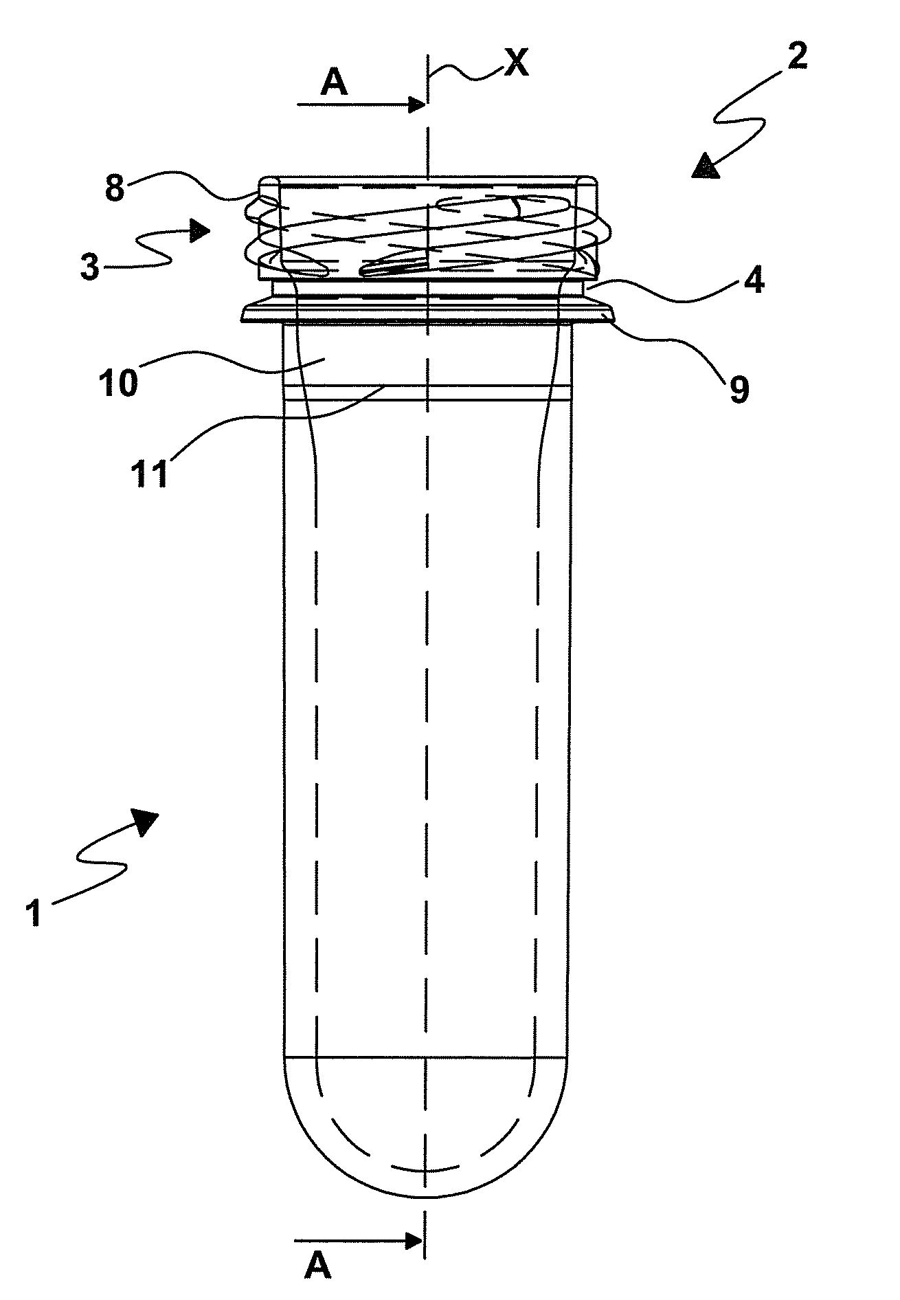
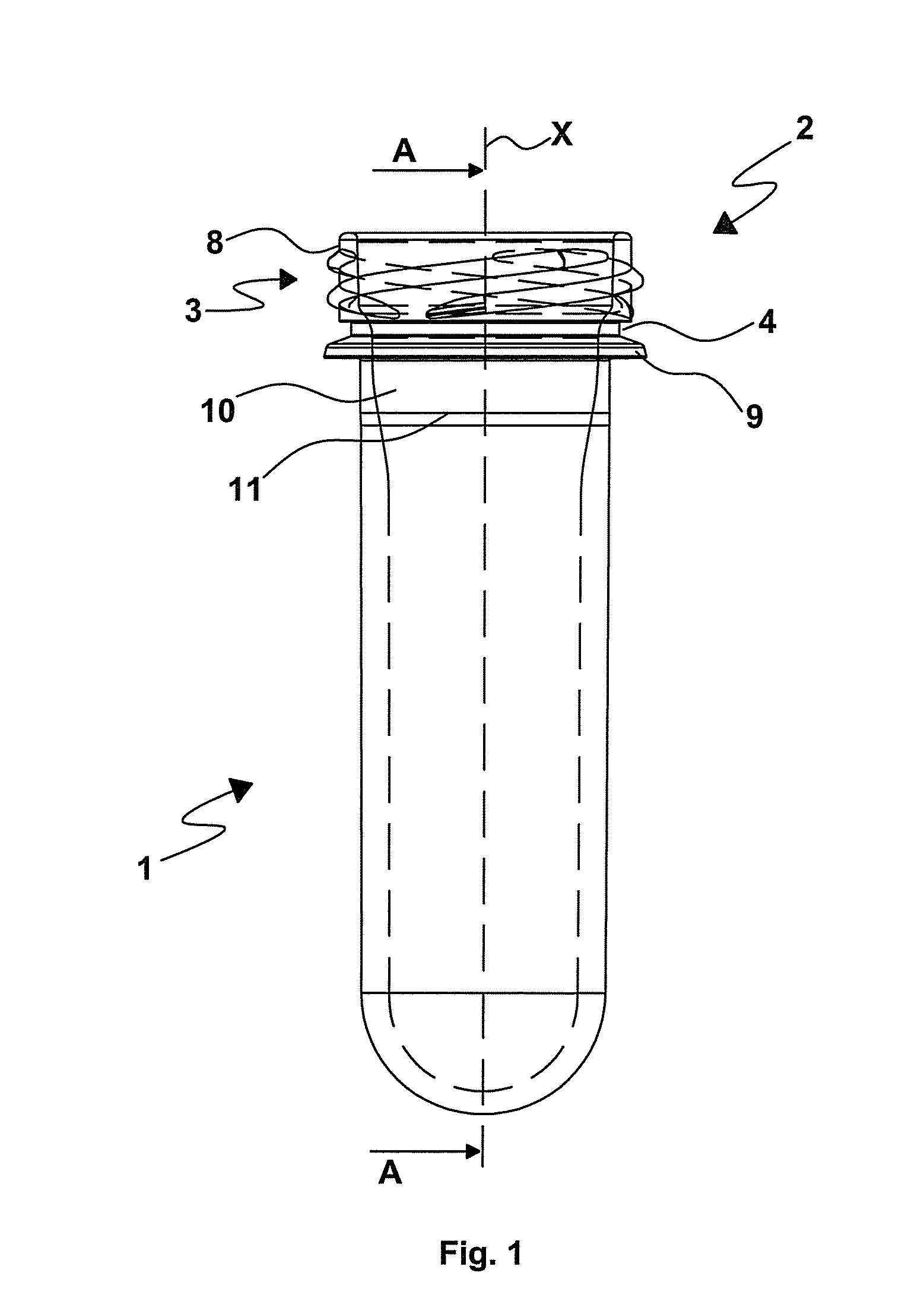
[0030]With reference to figures from 1 to 3, numeral 1 represents a plastic material preform, e.g. for manufacturing a beverage bottle, including a preferred embodiment of a bottle neck according to the present invention.

[0031]The preform 1, e.g. made of PET (Polyethylene terephthalate) or any other similar plastic material, is provided with a neck 2, defining a longitudinal axis X, which ends at the top in a cylindrical tubular segment 3, which is adapted to be sealed by a closure which, in turn, consists of a cup-shaped cap and an annular seal. Said annular seal is connected to the cup-shaped cap by means of a series of connecting joints having a scheduled rupture. Such joints serve the function of ensuring the complete sealing of the cap and the absence of possible tampering of the closure of the bottle.

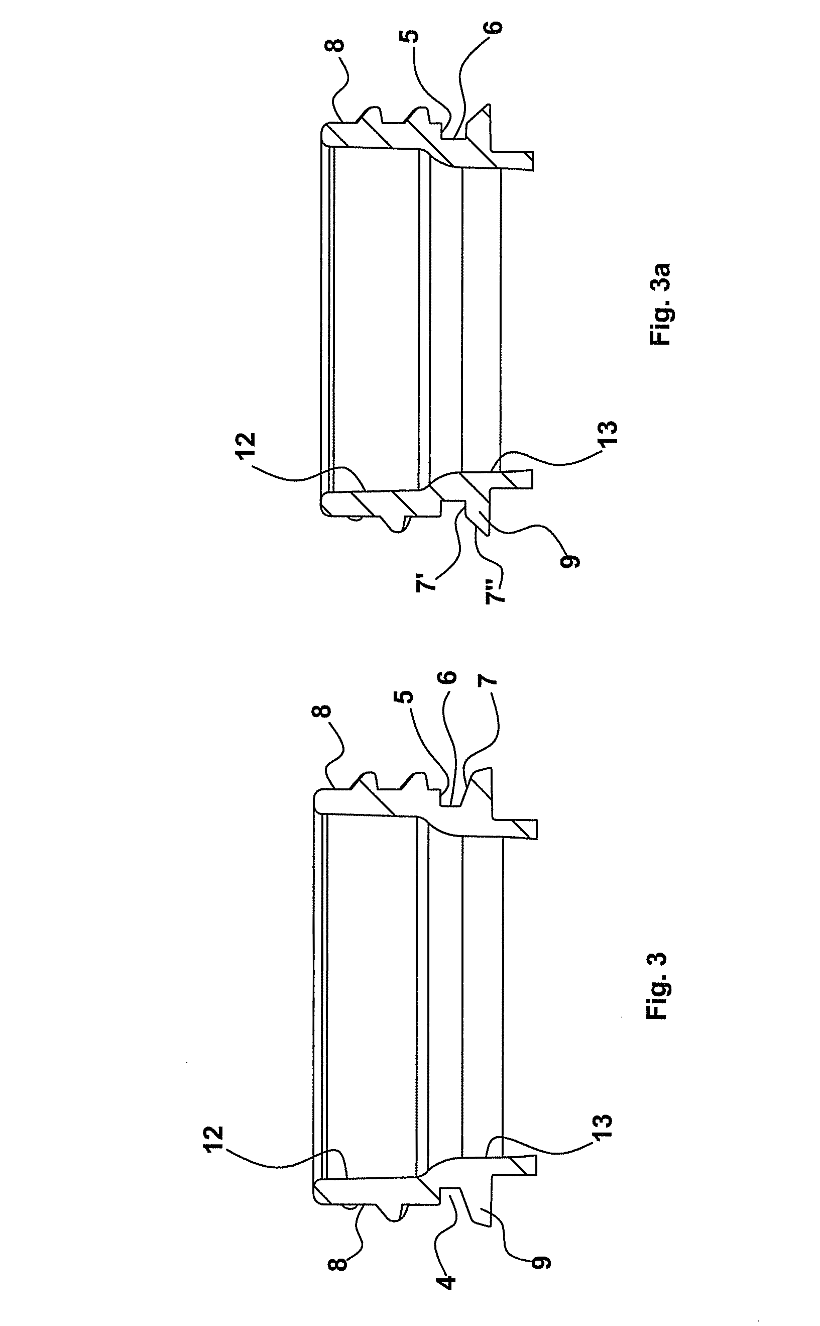
[0032]Specifically, the cylindrical tubular segment 3 includes a threaded end portion 8, onto which the cup-shaped cap is screwed, and a single annular ridge or neck ring 9, which...


PUM

PropertyMeasurementUnit
Angleaaaaaaaaaa
Angleaaaaaaaaaa
Angleaaaaaaaaaa

Abstract

A plastic material container, e.g. a beverage bottle, having a neck which requires the use of a smaller amount of plastic than the bottle necks of the prior art, and which is able to ensure a complete functionality for coupling the cap, ensuring at the same time the possibility of implementing the traditional supporting; sealing and handling operations of the bottle carried out during the various steps of manufacturing the same.

Description

FIELD OF THE INVENTION[0001]The present invention relates to a plastic material container, e.g. to a bottle intended to contain liquid for human consumption, such as beverages or mineral water.STATE OF THE ART[0002]The plastic material bottles which are currently intended to contain mineral water are normally provided with an upward tapered neck, which ends at the top in a cylindrical tubular segment, which is sealed by a closure which, in turn, consists of a cup-shaped cap and an annular seal. Such an annular seal is connected to the cup-shaped cap by means of a series of connecting joints having a scheduled rupture. Such joints serve the function of ensuring the complete sealing of the cup-shaped cap and the absence of possible tampering of the closure of said bottle.[0003]Specifically, the cylindrical tubular segment consists of:[0004]a threaded end portion onto which the cup-shaped cap may be screwed;[0005]a seal tearing crown positioned close to the lower end of the threaded en...

Claims


Application Information

Patent Timeline
IPC IPC(8): B65D1/02
CPCB29B11/08B29B11/14B29B2911/1402B29B2911/14026B29B2911/14033B29B2911/1404B29B2911/14106B29B2911/14133B29B2911/14326B29B2911/14333B29B2911/1442B29B2911/1444B29B2911/14573B29B2911/14753B29B2911/14793B29K2067/00B29K2105/258B29L2031/7158B65D1/023B65D1/0246B29C2949/28B29C2949/26B29C2949/24B29C2949/22B29C2949/3024B29C2949/3032B29C2949/072B29C2949/077B29C2949/073B29C2949/08B29C2949/0773B29C2949/0841B29C2949/0835B29C49/071B29C2949/0715
Inventor ZOPPAS, MATTEOZOPPAS, ENRICOEUSEBIONE, ERNESTO
Owner SIPA SOCIETA INDUSTRIALIZZAZIONE PROGETTAZIONE E AUTOMAZIONE SPA
Features
  • Generate Ideas
  • Intellectual Property
  • Life Sciences
  • Materials
  • Tech Scout
  • Unparalleled Data Quality
  • Higher Quality Content
  • 60% Fewer Hallucinations
Learn More