Mounting structure of electronic circuit unit

a technology of mounting structure and electronic circuit, which is applied in the direction of electrical apparatus casing/cabinet/drawer, semiconductor/solid-state device details, coupling device connections, etc., can solve the problems of difficult to ensure the mounting space of the casing, the inability to ensure the arrangement space of the mother board, and the inability to allow the occupation area of the mother board to be smaller than the bottom area of the casing, etc., to achieve a high space factor and increase the degree of design freedom

Inactive Publication Date: 2010-12-16
ALPS ALPINE CO LTD
View PDF1 Cites 8 Cited by
  • Summary
  • Abstract
  • Description
  • Claims
  • Application Information

AI Technical Summary

Benefits of technology

[0009]As described above, if the mounting structure is employed in which the electronic circuit unit is fixed to the set-side panel, instead of the mother board, and the electronic circuit unit is electrically connected to the mother board through the flexible cable, since the protruding direction of the F type connector can be arbitrarily selected with respect to the mother board, even if the mother board is arranged with respect to the set-side panel in any directions, the electronic circuit unit can be mounted without difficulty. For the same reason, in the case of set-side equipment, the relative position relationship between the set-side panel, from which the F type connector protrudes, and the mother board is not limited, resulting in an increase in the degree of freedom for design.
[0010]Further, a space on the mother board is necessary for connecting the end portion of the flexible cable, but no space is necessary for mounting the electronic circuit unit, so that an occupation area on the mother board can be significantly reduced, resulting in the obtaining of a high space factor.

Problems solved by technology

However, when designing the layout in which the F type connector protrudes transversely, problems may occur in which an arrangement space of the mother board cannot be ensured.
In addition, according to the existing electronic circuit unit, even if the size of the casing is reduced as much as possible, it may not be possible to allow an occupation area on the mother board to be smaller than a bottom area of the casing.
In this regard, if a mounting density of parts on the mother board increases, problems may occur in which it is difficult to ensure a mounting space of the casing.

Method used


Image

  • Mounting structure of electronic circuit unit
  • Mounting structure of electronic circuit unit
  • Mounting structure of electronic circuit unit

Examples


Embodiment Construction

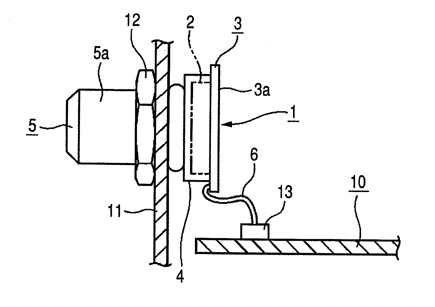
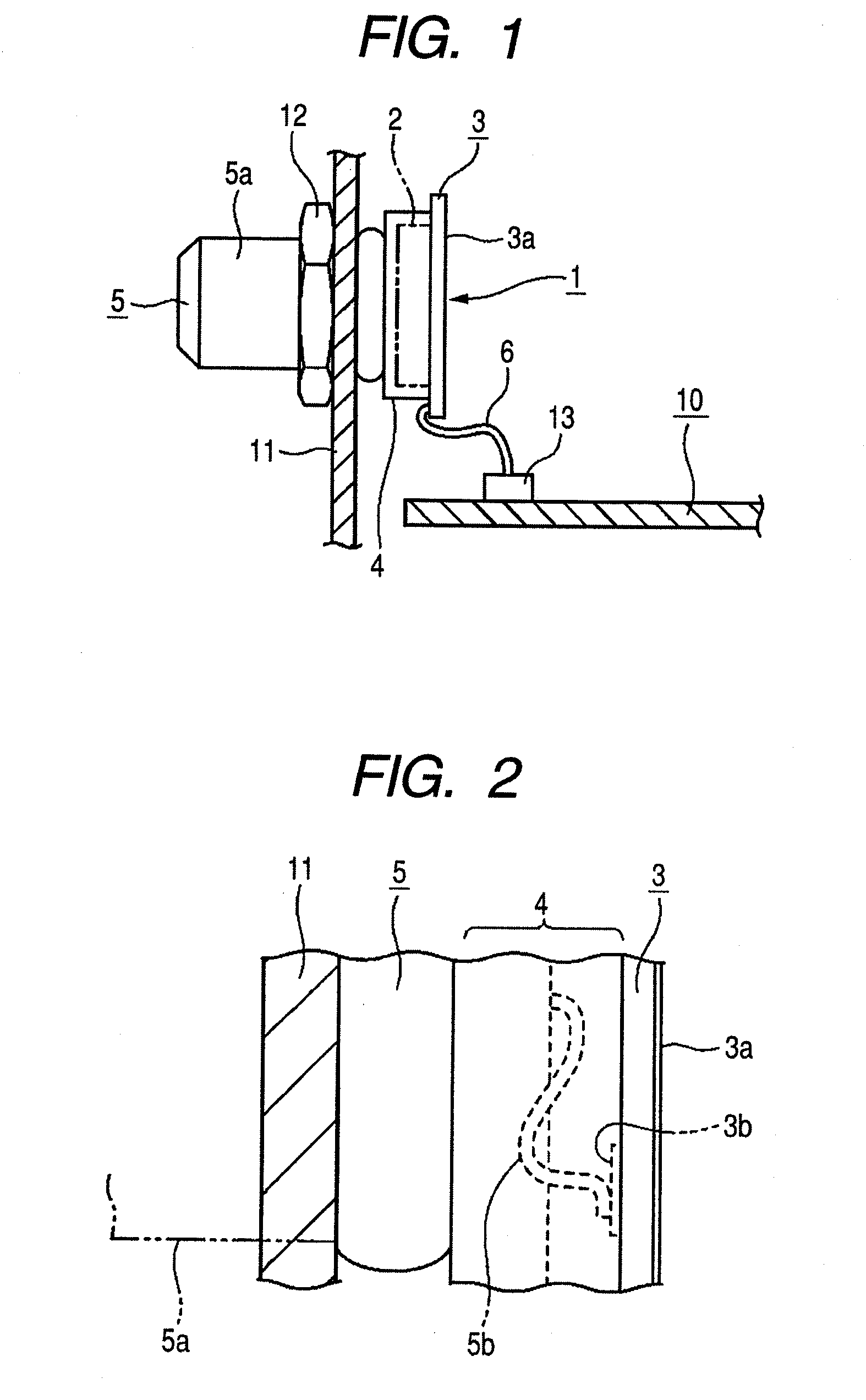
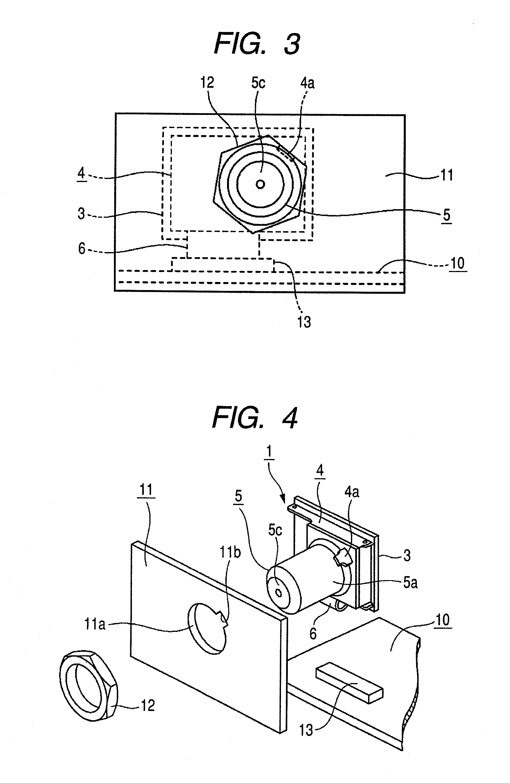
[0018]Hereinafter, embodiments of the invention will be described with reference to FIGS. 1 to 7. An electronic circuit unit 1 shown in FIGS. 1 to 7 is a tuner unit for receiving a television broadcast, and is mounted on set-side equipment such as a television receiver provided with a mother board 10 and a panel 11. FIGS. 1 to 4 illustrate the electronic circuit unit 1 mounted on the set-side equipment in which the mother board 10 is arranged approximately perpendicularly to the panel 11, and FIGS. 6 and 7 illustrate the electronic circuit unit 1 mounted on the set-side equipment in which the mother board 10 is arranged approximately parallel to the panel 11.

[0019]The electronic circuit unit 1 mainly includes a circuit board 3 provided with a high frequency circuit 2 including a part or the whole of a tuner circuit, a metallic casing 4 mounted on the circuit board 3 to cover the high frequency circuit 2, an F type connector 5 from which a cable connector (not shown) for a coaxial ca...


PUM


Abstract

A mounting structure of an electronic circuit unit includes a circuit board provided with a high frequency circuit, a metallic casing mounted on the circuit board to cover the high frequency circuit, an F type connector fixed to the casing and protruding approximately perpendicularly to the circuit board, and a flexible cable having one end portion connected to the circuit board. In a state in which the F type connector passes through a mounting hole formed through a set-side panel to protrude outward, at least one of the casing and the F type connector is fixed to the set-side panel by a fixing member, and the other end portion of the flexible cable is connected to a mother board.

Description

CROSS REFERENCE TO RELATED APPLICATION[0001]The present invention contains subject matter related to and claims priority to Japanese Patent Application JP 2009-142154 filed in the Japanese Patent Office on Jun. 15, 2009, the entire content of which is incorporated herein by reference.BACKGROUND[0002]1. Technical Field[0003]The present invention relates to a mounting structure of an electronic circuit unit provided with an F type connector, which is suitable as a small-sized tuner unit for receiving a television broadcast.[0004]2. Related Art[0005]Recently, with the spread of slim televisions, there are increasing demands for the miniaturization of a tuner unit for receiving television broadcasts. This type of tuner unit mainly includes a circuit board provided with a high frequency circuit including a part or the entire tuner circuit, a metallic shield cover mounted on the circuit board to cover the high frequency circuit, and an F type connector from which a cable connector for a c...

Claims


Application Information

Patent Timeline
Patent Type & Authority Applications(United States)
IPC IPC(8): H03J1/00H05K5/00H01L23/32H01R12/00H01R12/62H01R12/77H01R13/73H01R24/38H01R24/76H04B1/08H04N5/44H04N5/64
CPCH01R12/77H01R24/52H04N5/655H05K5/0247
Inventor MATSUZAKI, SATORU
Owner ALPS ALPINE CO LTD
Why Eureka
Try Eureka