Geodetic scanner with increased efficiency

a geodetic scanner and efficiency technology, applied in the field of systems and methods for surveying, can solve the problems of inaccurate distances determined from return signals having a too large or too low power, unnecessary processing of invalid measurements, and inability to achieve alternative, etc., to achieve the effect of reducing the average power that is received by the eye, increasing the overall measurement rate, and reducing the exposure time of the eye per time interval

Active Publication Date: 2010-12-16
TRIMBLE INC
View PDF5 Cites 18 Cited by
  • Summary
  • Abstract
  • Description
  • Claims
  • Application Information

AI Technical Summary

Benefits of technology

[0018]The present invention achieves a number of advantages. For instance, the scanner and method of the present invention are advantageous in that the beam is continuously kept in motion. As compared with the two-step measurement method for instance, the overall measurement rate is increased.
[0019]Further, as the beam is continuously kept in motion in the present invention, the exposure time for a person's eye per time interval is reduced. Generally, the amount of light an eye can tolerate depends on the intensity, the wavelength and the duration of irradiation. With respect to laser regulations for eye safety, the energy to which an eye may be exposed under a certain period of time must not exceed a predefined value. For a similar density of positions at a surface of an object, for a scanner according to the present invention as compared to a conventional scanner using a two-step measurement method, an eye may be exposed to the same amount of energy but the exposure time is spread over a longer period of time with the present invention. Indeed, distance measurements are performed once all gain values have been determined instead of after every determination of a gain value as in a two-step measurement method. In other words, a longer period of time has lapsed between the exposure for determination of a gain value at a particular position and the exposure for distance measurement at the same position. As a result, with the present invention, the average power that is received by an eye is reduced.
[0020]Further, while complying with the above mentioned laser regulations, the output power of the laser could be increased since the exposure time for a person's eye per time interval is reduced. An increase of the laser output power would be advantageous since it would increase the signal to noise ratio of the signal used to calculate the distance, thereby providing more accurate measurements.
[0021]Further, the present invention is advantageous in that it reduces power consumption. Referring again to prior art scanners, high power consumption is required each time the scanner needs to move from one position to another because of the required acceleration. In a worst-case scenario, the acceleration required for rotating a conventional scanner from one position to an another may be so high that the deflection motor may burn because of a too high applied power. In the present invention, the scanner is always in motion during measurements.
[0022]According to an embodiment, the distance from the scanner may be measured for at least one intermediate position located between at least two predetermined positions using a gain value estimated from the two determined gain values associated with the two predetermined positions. This embodiment is advantageous since the initial scan is performed to calculate gain values for only a sub-set of the positions to which distances are measured. As a result, the measurement rate and the overall efficiency are increased.

Problems solved by technology

As a result, distances determined from a return signal having a too large or too low power are not accurate because of difficulties in handling a wide dynamic range at the measuring device (scanner).
The detected signal may e.g. be saturated or subject to too much noise.
However, such an alternative is not desirable since the appearance of the target object is determined from a limited number of valid measurements only, i.e. with a reduced resolution.
Further, this method implies unnecessary processing of invalid measurements.
However, a drawback of such a method and scanner is the limited measurement rate, and thereby rather low overall efficiency.

Method used


Image

  • Geodetic scanner with increased efficiency
  • Geodetic scanner with increased efficiency
  • Geodetic scanner with increased efficiency

Examples


Embodiment Construction

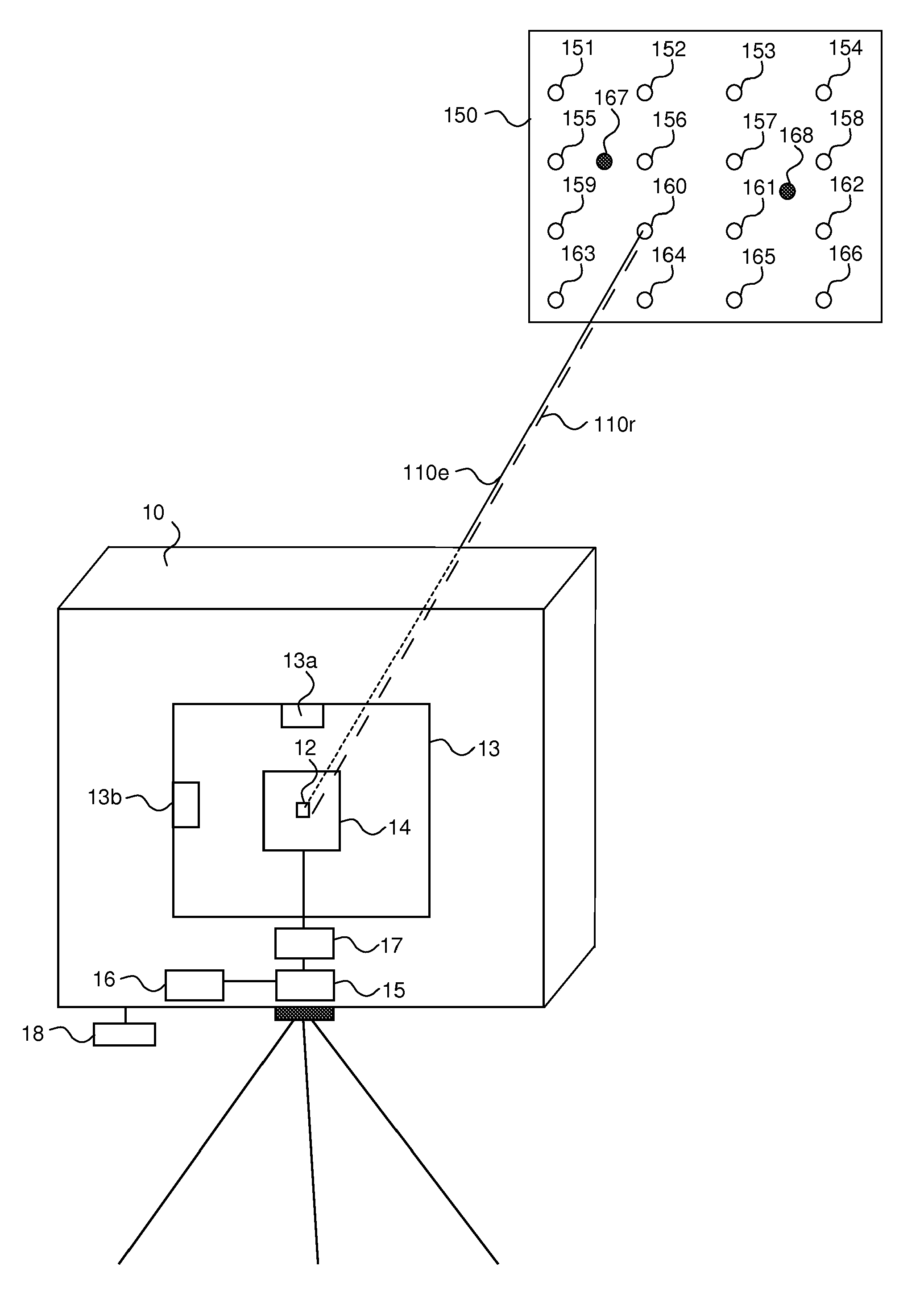
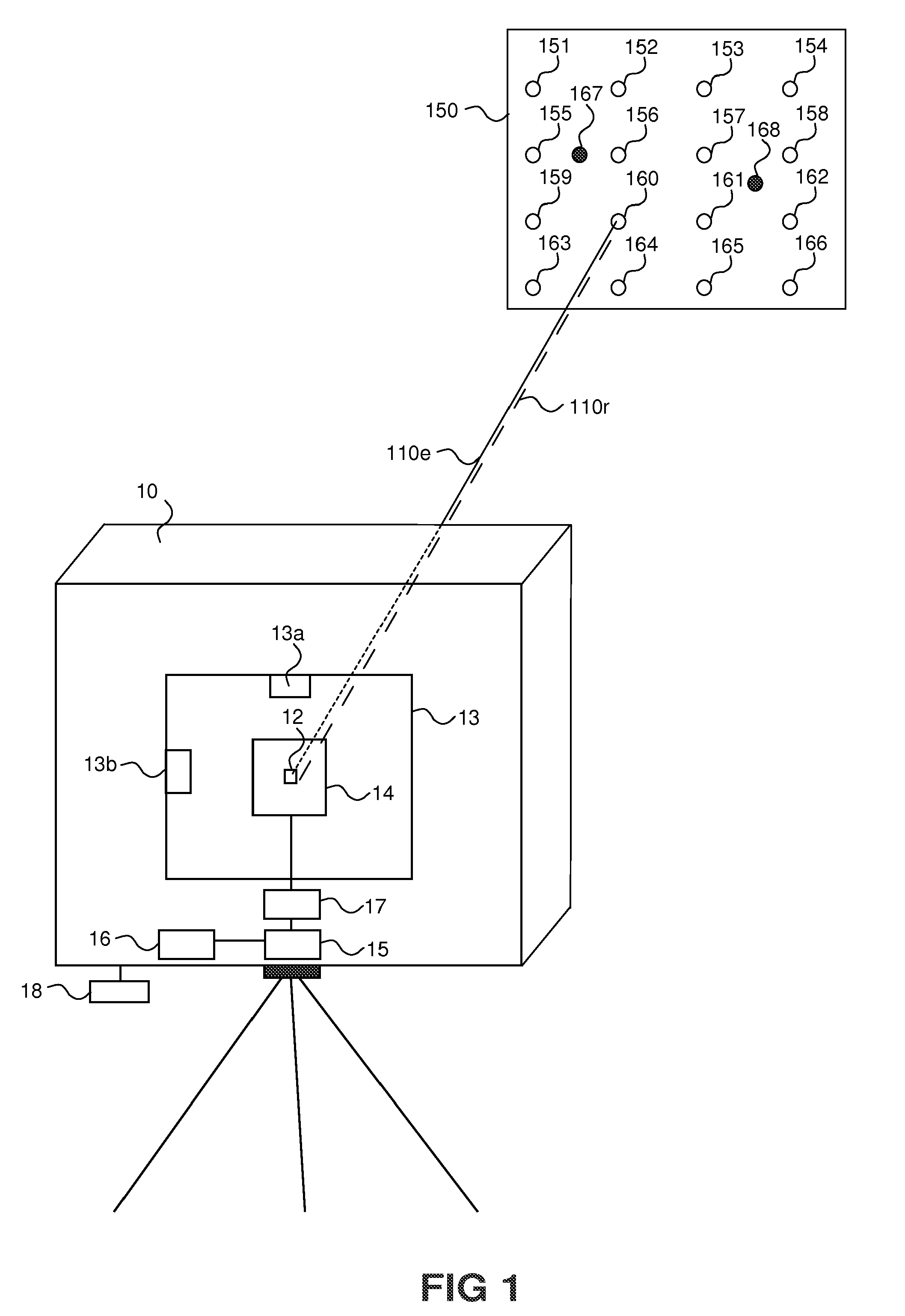
[0036]With reference to FIG. 1, a geodetic scanner 10 implementing a scanning procedure according to an embodiment of the present invention is described.

[0037]In the present embodiment, the geodetic scanner 10 determines the appearance of a target 150, for example a wall, by scanning over a number of predetermined positions 151-166.

[0038]The number of predetermined positions to be measured may be manually selected by a user, e.g. by entering data via a keyboard 18 of the geodetic scanner 10. For example, the user may select a number of measurements to be performed per angle unit, e.g. one measurement every grad. As another example, the geodetic scanner 10 may comprise a camera (not shown), such as a CCD or a CMOS, for displaying an image of the target to the user who may then select a number of points corresponding to a number of positions at the surface of the target. Alternatively, the user may select a region of interest in the image and enter a desired number of positions. The d...


PUM


Abstract

The present invention provides a method and a geodetic scanner for determining the appearance of a target. In the method and geodetic scanner of the present invention, an initial can is performed to calculate or determine a set of optimal gain values for each one of a number of predetermined positions (151-166) at the surface of the target (150). Once gain values (g151-g166) have been determined for all predetermined positions, distances to each one of the predetermined positions are calculated using the gain values. The present invention is advantageous in that the measurement rate and the overall efficiency are increased.

Description

FIELD OF THE INVENTION[0001]The present invention generally relates to systems and methods for surveying and more specifically to a method and a scanner for determining the appearance of a target. The present invention relates in particular to methods and geodetic instruments for scanning a surface or volume of an object.BACKGROUND ART[0002]The art of surveying involves the determination of unknown positions, surfaces or volumes of objects using measurements of angles and distances. In order to make these measurements, a surveying instrument frequently comprises an electronic distance measuring device (EDM) which may be integrated in a so-called total station. A distance measuring total station combines electronic, optical and computer techniques and is furthermore provided with a computer or control unit with writable information for controlling the measurements to be performed and for storing data obtained during the measurements. Preferably, the total station calculates the posit...

Claims


Application Information

Patent Timeline
Patent Type & Authority Applications(United States)
IPC IPC(8): G01C3/00G06F19/00G01S17/86G01S17/89
CPCG01S7/483G01S7/4868G01S7/497G01S17/023G01S17/42G01S17/89G01S17/86
Inventor HERTZMAN, MIKAEL
Owner TRIMBLE INC
Why Eureka
Try Eureka