Electro-optic distance-measuring device

a technology of optical distance measurement and measuring device, which is applied in the direction of measurement device, using reradiation, instruments, etc., can solve the problems of limiting the measurement rate (to e.g. 20 hz), and the inability of known single-pass modulators to meet the needs of measuremen

Active Publication Date: 2015-03-19
LEICA GEOSYSTEMS AG
View PDF3 Cites 6 Cited by
  • Summary
  • Abstract
  • Description
  • Claims
  • Application Information

AI Technical Summary

Benefits of technology

[0036]The symmetrical configuration allows to get the same electro-optic response in th

Problems solved by technology

The two resulting linear waves can now interfere.
Setting a particular modulation frequency requires mechanical tuning of the resonator, thus limiting the measurement rate (to e.g. 20 Hz).
How

Method used


Image

  • Electro-optic distance-measuring device
  • Electro-optic distance-measuring device
  • Electro-optic distance-measuring device

Examples


Embodiment Construction

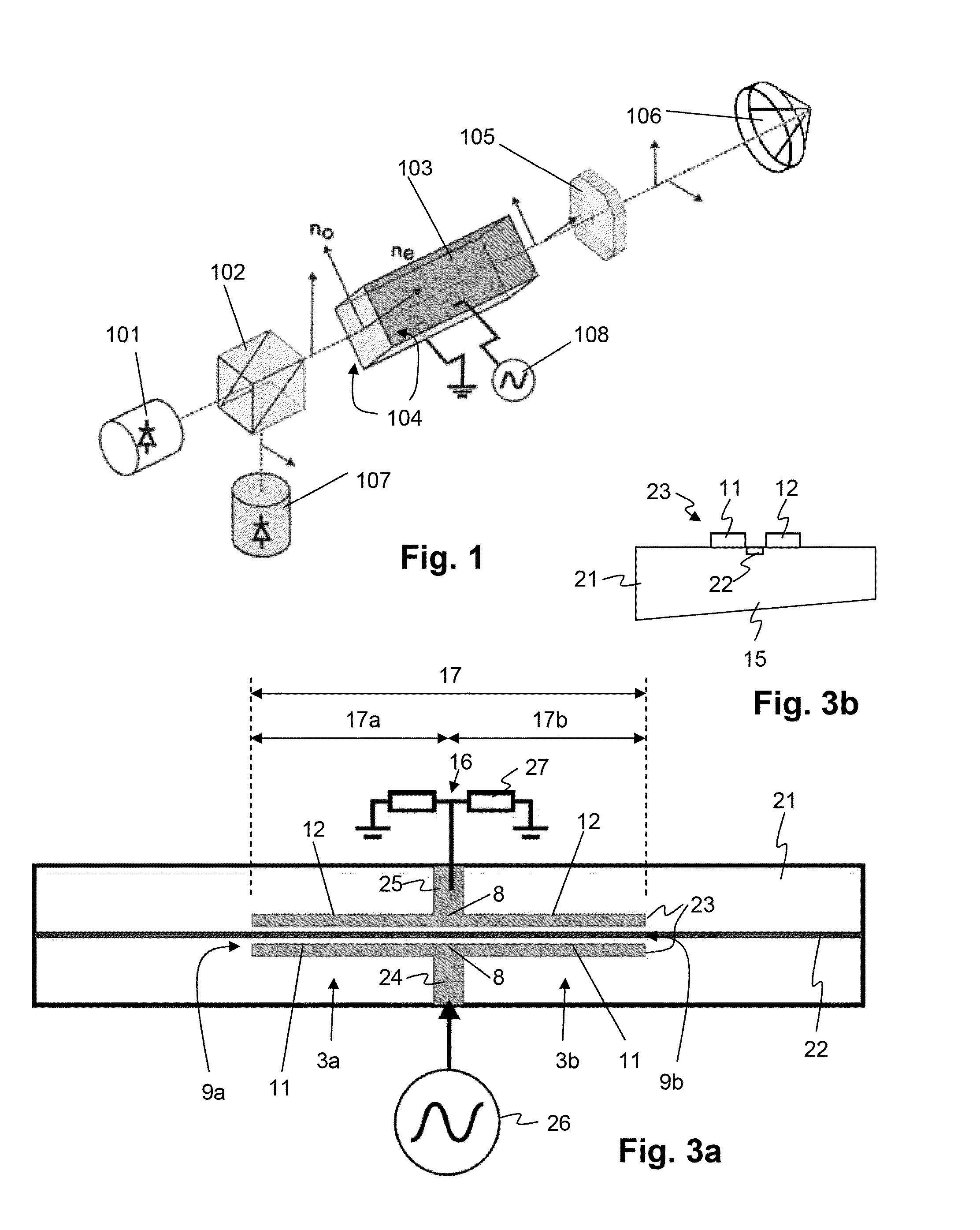
[0042]In principle, identical parts are provided with the same reference symbols in the Figures.

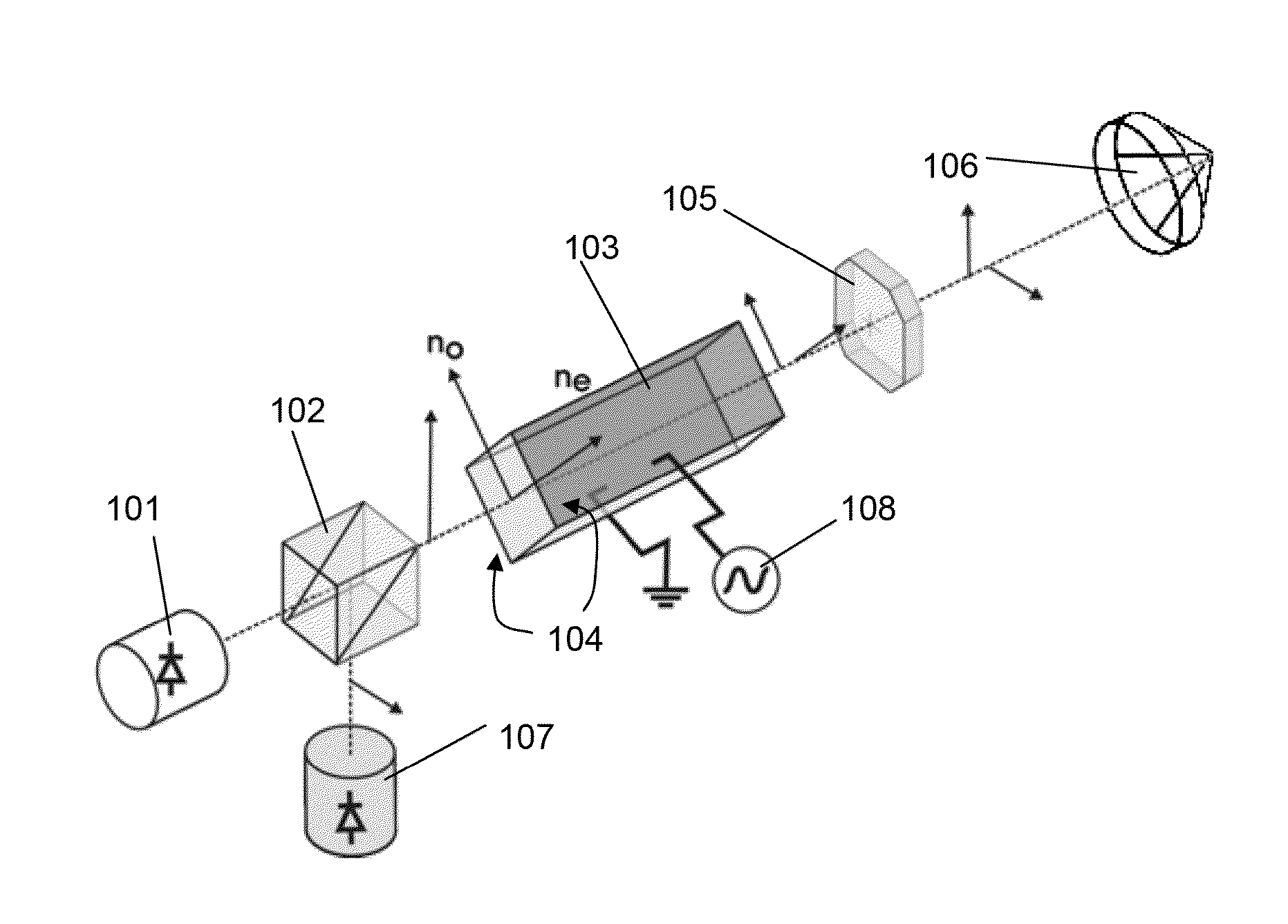
[0043]Convention: A phase modulator uses an electro-optic crystal. The index of modulation will define the so-called half wave voltage Vπ. The half-wave voltage is a characteristic of an electro-optic modulator and corresponds to the voltage that needs to be applied to the crystal in order to modify the optical phase of transmitted light by π-radians.

[0044]A guided wave configuration of an electro-optic modulator is as follows: a straight optical waveguide is shaped in a crystal surface, allowing the confinement of light in a small channel whose cross section is of some micrometers in width and height. Coplanar electrodes are arranged near the waveguides with a gap of some micrometers, application of a strong electric field to the waveguide. The half wave voltage can reduced to a few volts, much less than for bulk crystal modulators.

[0045]Guided wave modulators in, e.g. lithium niobate, c...


PUM


Abstract

A distance measuring device includes a light source emitting light, and an integrated electro-optic modulator arranged such that the emitted light passes through an optical waveguide of the electro-optic modulator in a first direction before being emitted from the distance measuring device, and after being reflected from a target passes through the electro-optic modulator in a second direction which is opposite to the first direction. The forward electro-optic response of a modulating region of the electro-optic modulator is the same as the backward electro-optic response, and a center of gravity of the modulation is independent of modulation frequency.

Description

BACKGROUND OF THE INVENTION[0001]1. Field of the Invention[0002]The invention relates to au electro-optic distance measuring device.[0003]2. Description of Related Art[0004]Relevant distance-measuring devices are known from EP 0 205 406, EP 0 313 518, EP-A-1 647 838, WO 97 / 18486 and EP patent application number 10 405 078, for example. The content of these applications is incorporated in their entirety by reference for elucidating the functioning of the Fizeau method for absolute distance measurement. U.S. Pat. No. 3,424,531 describes a distance measurement device using a light modulator that turns light transmission on and off, similar to a rotating tooth-weel.[0005]FIG. 1 schematically shows a distance measuring device for measuring absolute distance according to the prior art: A light source 101 emits light, typically in the visible or infrared range, with center wavelength λ, the spectral width of the source being broad enough in order to ensure a low coherence light emission. T...

Claims


Application Information

Patent Timeline
IPC IPC(8): G01S17/32G01S7/499G01B11/14G01S7/491
CPCG01S17/32G01S7/499G01B11/14G01S7/481G01S7/491G01S17/36
Inventor LUTHI, THOMASBOCKEM, BURKHARD
Owner LEICA GEOSYSTEMS AG
Why Eureka
Try Eureka