Moving picture coding device and broadcast wave recording device

a technology of moving picture and coding device, which is applied in the direction of signal generator with optical-mechanical scanning, color television with bandwidth reduction, etc., can solve problems such as buffer overflow, and achieve the effect of stable image quality and reducing the amount of bits

Inactive Publication Date: 2010-12-16
PANASONIC INTELLECTUAL PROPERTY MANAGEMENT CO LTD
View PDF20 Cites 35 Cited by
  • Summary
  • Abstract
  • Description
  • Claims
  • Application Information

AI Technical Summary

Benefits of technology

[0016]The moving picture coding device in the present invention enables reducing the amount of bits to be generated, for example, even when a picture that is inputted and coded in the middle of a current control target group such as a GOP has an extremely complicated content, according to a method of coding quantization matrices all together at the beginning of the control target group. Therefore, the moving picture coding device is capable of generating a stream having a stable image quality without causing buffer overflow.FURTHER INFORMATION ABOUT TECHNICAL BACKGROUND TO THIS APPLICATION

Problems solved by technology

Therefore, there is a possibility of causing buffer overflow in the case where an extremely complicated picture is locally inputted in the middle of the current GOP.

Method used


Image

  • Moving picture coding device and broadcast wave recording device
  • Moving picture coding device and broadcast wave recording device
  • Moving picture coding device and broadcast wave recording device

Examples


embodiment 1

[0057]Embodiment 1 according to the present invention will be described below with reference to the drawings.

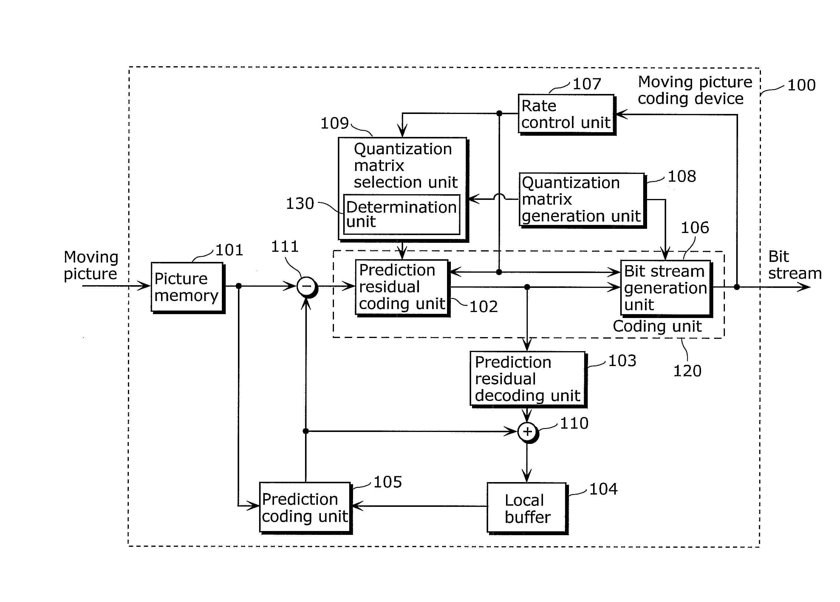
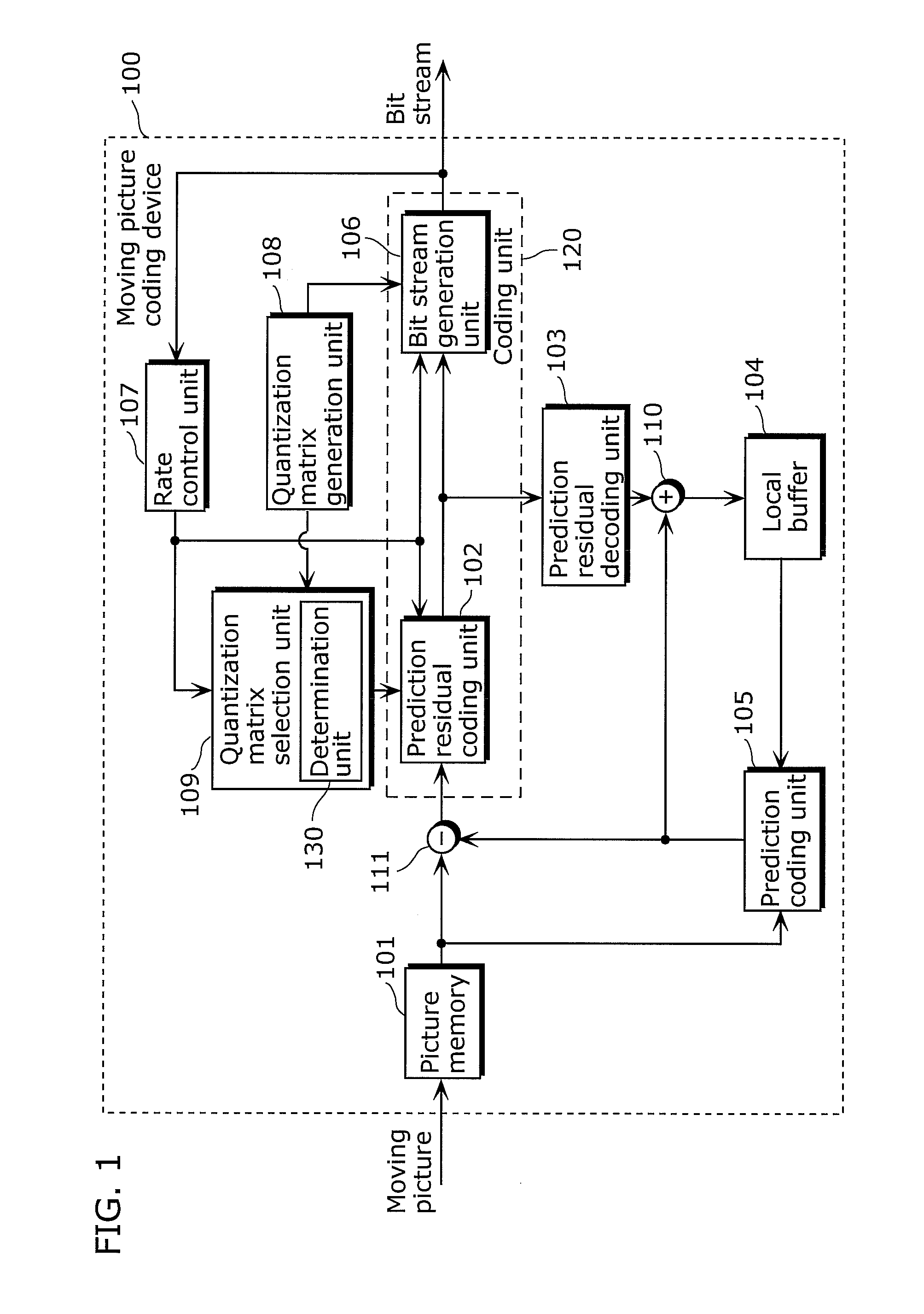
[0058]A moving picture coding device according to Embodiment 1 in the present invention includes: a quantization matrix generation unit which generates (i) normal quantization matrices each of which is used in a quantization process according to normal rate control and (ii) a quantization matrix for bit amount reducing which is used when strong bit amount reducing is determined to be required compared to the case of performing the quantization process according to the normal rate control, more specifically, strong bit amount reducing is required which reduces the amount of bits to be generated in the quantization process according to such reducing more effectively than the amount of bits to be generated in the quantization process according to normal rate control; and a coding unit which stores the normal quantization matrices and the quantization matrix for bit amount reduci...

embodiment 2

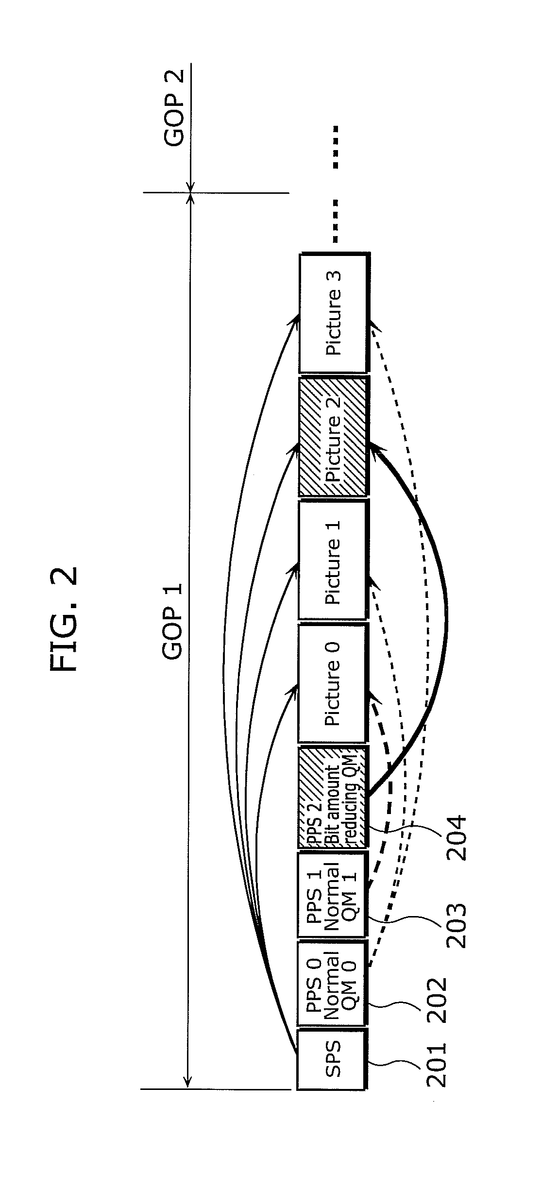
[0126]In Embodiment 1, it is assumed that the QMs generated by the quantization matrix generation unit 108 are the normal QMs and the bit amount reducing QM which are predefined and directly coded. However, the bit amount reducing QM may be generated even if it is not required in quantizing a picture within a GOP, and thus produces a problem of disabling efficient use of the header of the GOP.

[0127]For this, in Embodiment 2, a quantization matrix generation unit determines whether or not to generate a bit amount reducing QM using a result of buffer simulation, and generates the bit amount reducing QM with a determination that the bit amount reducing QM should be generated.

[0128]Next, a moving picture coding device according to Embodiment 2 is described with reference to the drawings.

[0129]FIG. 7 is a block diagram showing an exemplary structure of the moving picture coding device 700 in Embodiment 2.

[0130]The moving picture coding device 700 shown in FIG. 7 differs from the moving p...

embodiment 3

[0149]In Embodiments 1 and 2, the bit amount reducing QMs generated by a corresponding one of the quantization matrix generation units 108 and 708 are set as predefined constant value matrices. However, the amounts of bits accumulated in the buffer change as current moving pictures to be inputted change. The amounts of accumulated bits are generated by the rate control unit 707. Along this, it is preferable that the bit amount reducing QM is modified suitably for each GOR

[0150]For this, in Embodiment 3, the quantization matrix generation unit generates, for each of GOPs, a bit amount reducing QM having a set of coefficient values different from a set of coefficient values of any other one of the QMs, based on the result of buffer simulation.

[0151]Next, a moving picture coding device according to Embodiment 3 is described with reference to the drawings.

[0152]FIG. 9 is a block diagram showing an exemplary structure of the moving picture coding device 900 in Embodiment 3.

[0153]The movi...


PUM


Abstract

A device coding a moving picture in units of a group including pictures, including: a generation unit generating quantization matrices; a selection unit selecting a quantization matrix for a current picture; a unit storing the quantization matrices in a header part of the group, and coding the current picture; a unit including a virtual buffer, and performing buffer simulation based on an amount of bits to be outputted; and a unit determining whether bit amount reducing is required for the current picture, based on a result of the buffer simulation, wherein the generation unit generates a normal quantization matrix used in common for at least one of the pictures, and a quantization matrix for bit amount reducing used only when the bit amount reducing is required, and the selection unit selecting the quantization matrix for bit amount reducing used for the current picture, when the bit amount reducing is required.

Description

BACKGROUND OF THE INVENTION[0001](1) Field of the Invention[0002]The present invention relates to moving picture coding devices and broadcast wave recording devices which convert input moving pictures into coded signals representing information obtained by compressing data of moving pictures, and particularly relates to methods of coding quantization matrices.[0003](2) Description of the Related Art[0004]General methods of coding moving pictures involve compressing the information amounts of the moving pictures by reducing redundancies in the temporal and spatial directions. A picture that is subjected to intra-picture prediction coding without reference to any reference picture is referred to as an I-picture (Intra-picture). The intra-picture prediction coding is performed with an aim to reduce redundancy in the spatial direction. In addition, a picture that is subjected to inter-picture prediction coding with reference to only a single reference picture is referred to as a P-pictu...

Claims


Application Information

Patent Timeline
Patent Type & Authority Applications(United States)
IPC IPC(8): H04N7/26H04N19/126H04N19/50H04N19/134H04N19/136H04N19/146H04N19/152H04N19/177H04N19/196H04N19/423H04N19/46H04N19/503H04N19/60H04N19/61H04N19/70H04N19/91
CPCH04N19/176H04N19/46H04N19/61H04N19/126H04N19/152
Inventor ABE, KIYOFUMIARAKAWA, HIROSHIJURI, TATSUROTSUDA, KENJIROOHGOSE, HIDEYUKI
Owner PANASONIC INTELLECTUAL PROPERTY MANAGEMENT CO LTD
Why Eureka
Try Eureka