Powered painting system

a technology of power-fed paint brushes and rollers, which is applied in the direction of brushes, carpet cleaners, coatings, etc., can solve the problems of previously known power-fed paint brushes that do not have the control of paint brushes, and do not provide the distinct and often desirable finish of paint brushes, so as to achieve effective, dynamic cleaning action and effectively clean the bristles of paint brushes

Active Publication Date: 2010-12-16
TOTE CONNECTION
View PDF27 Cites 8 Cited by
  • Summary
  • Abstract
  • Description
  • Claims
  • Application Information

AI Technical Summary

Benefits of technology

[0008]In one embodiment, the present invention comprises a pressurized fluid (typically paint) fed paint brush which has a paint distribution system which delivers paint to the proper portion of the bristles and does not unduly inhibit the proper flexure of the bristles when painting with strokes in a direction perpendicular to the wide dimension of the bristles (primary stroke) or in a direction parallel to the wide dimension of the bristles (edge stroke).
[0017]In order to clean the powered paint roller or powered paint brush, a cleaning device is provided. The cleaning device may comprise a garden spigot connector connected to one end of a tube. The other end of the tube is connectable to the paint inlets of the paint roller and / or powered paint brush. The spigot connector is connected to a garden spigot, and the water is turned on to clean the paint roller or paint brush. For the powered paint roller, the shutoff valve to the cleaning jet is opened, so that water is sprayed onto the outer surface of the paint roller. The second cleaning shutoff valve may be left open to clean the interior of the roller axle or closed to direct the flow only to the cleaning jet. For the powered paint brush, the bristles and springs are flexed to allow water to flow through the springs and onto the bristles. Thus, the powered paint roller and / or powered paint brush can be quickly and easily cleaned after use.
[0019]The pressurized fluid paint brush may also be cleaned with the cleaning system described above. In a very advantageous aspect, the capped distribution members may provide an effective, dynamic cleaning action. By adjusting the water pressure connected to the cleaning system to be high enough to overcome the sealing effect of the fluid distribution members (for example, sufficient pressure to extend a spring from its closed pitch configuration), the distribution members move around in a random motion. This is similar to the end of a water hose when it is released with water flowing at a high pressure from the end of the hose. This dynamic cleaning action very effectively cleans the bristles of the paint brush.

Problems solved by technology

However, these alternative painting devices still do not have the control of a paint brush, nor do they provide the distinct and often desirable finish of paint brush.
However, these previously known power-fed paint brushes have a number of drawbacks.
For one, the tube connecting the paint brush to the paint reservoir can be a nuisance because it gets in the way of the painting motion and makes it harder to perform the typical back and forth painting strokes.
In addition, the paint distribution devices are ineffective for various reasons.
This creates problems with dripping and the flow of the paint to the lower end of the bristles and application to a surface being coated.
And for those distribution devices which do extend to near the lower end of the bristles, the devices tend to inhibit the proper flexure of the bristles during painting.
Although the inserts are disclosed as being flexible, it can be seen that such a device is very stiff in the transverse direction (i.e. the insets flex along with the bristles when bent by using the wide plane of the brush, but is very stiff when bent by using the narrow edge of the brush).

Method used


Image

  • Powered painting system
  • Powered painting system
  • Powered painting system

Examples


Embodiment Construction

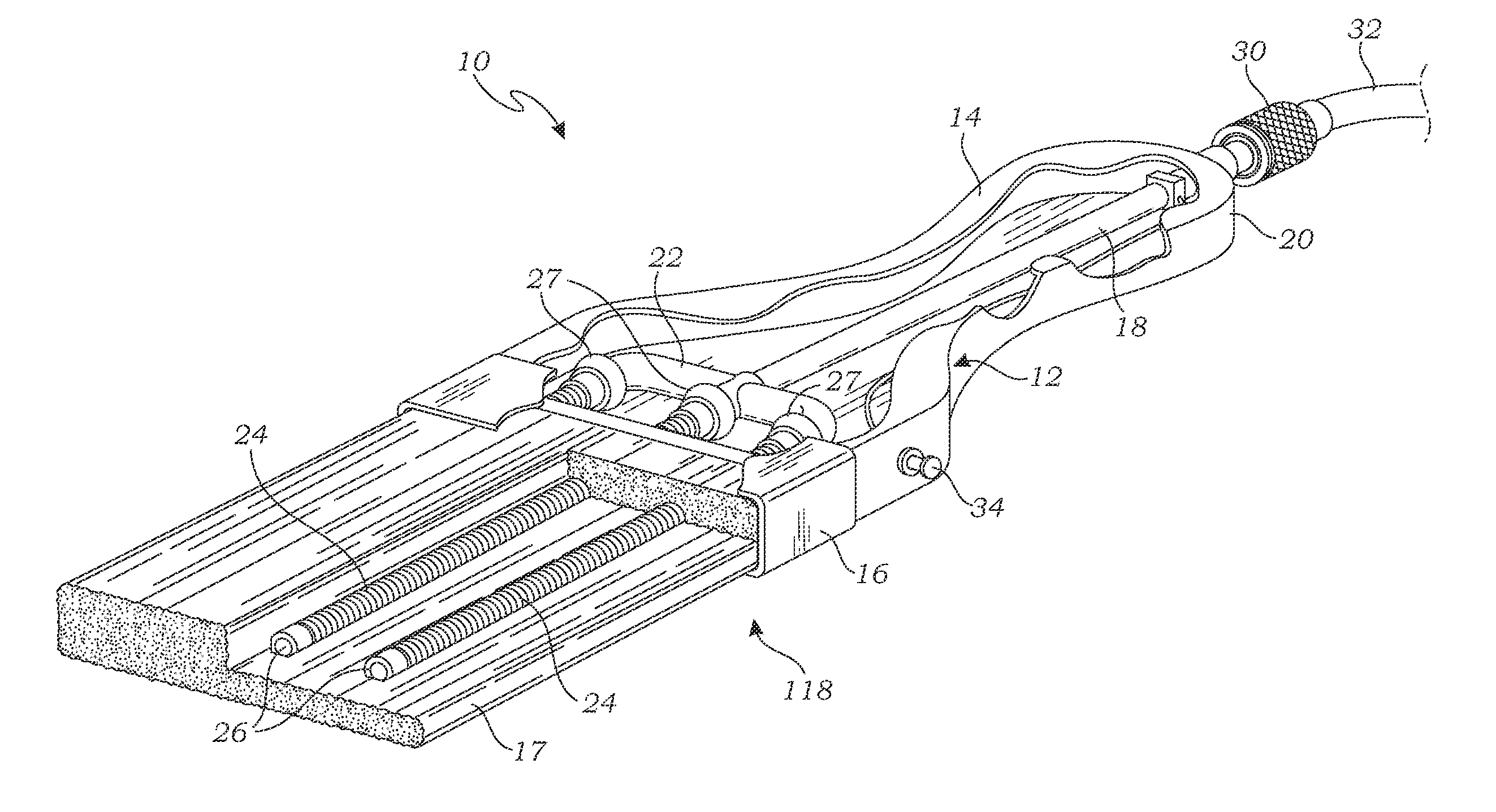
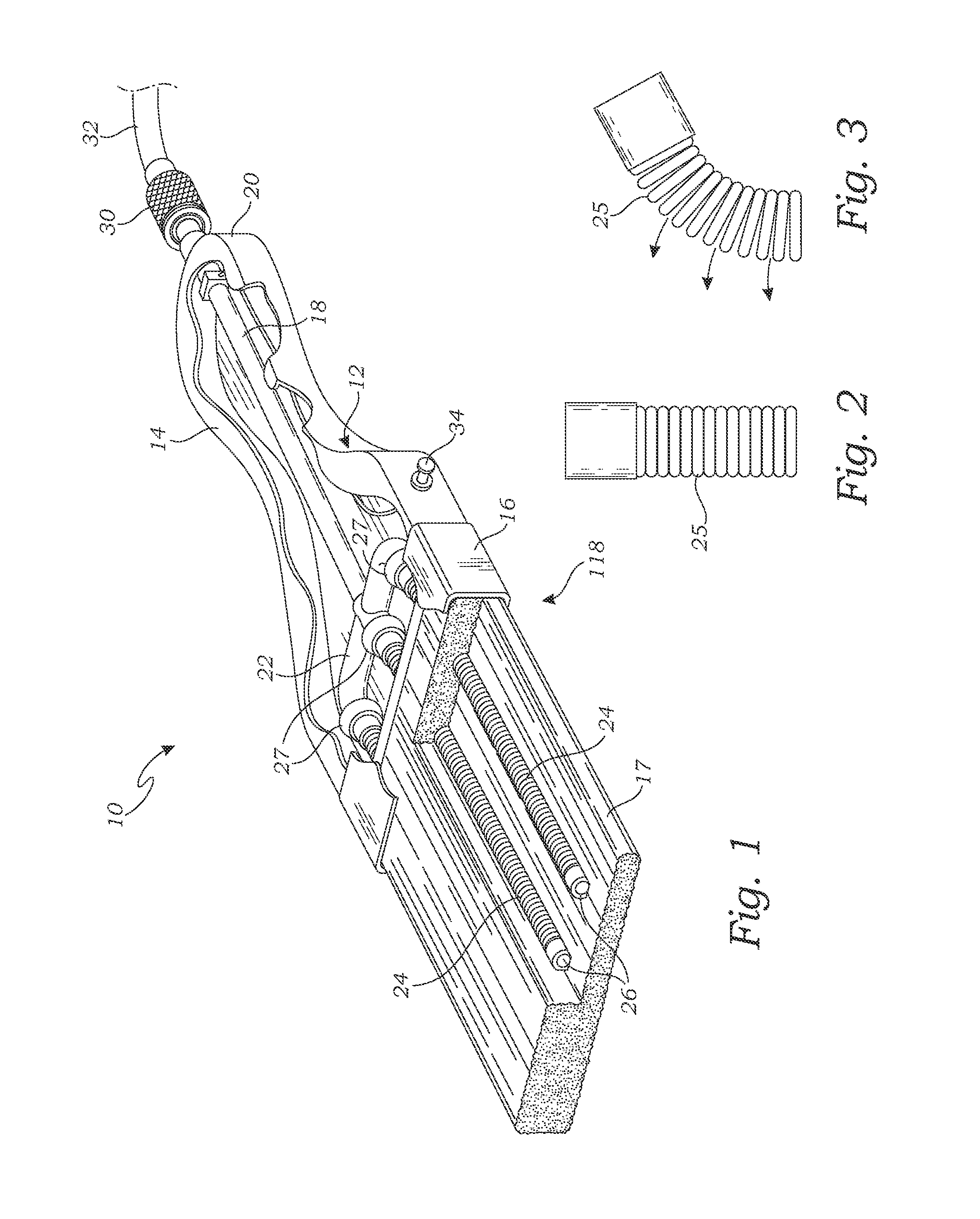
[0036]Turning to FIG. 1, a power fed paint brush 10 according to the present invention is shown. The power fed paint brush 10 comprises a main body 12 having a handle 14 and a bristle stock 16. A bristle bundle 17 is retained by the bristle stock 16. The main body 12 may be formed of any suitable material such as wood, plastic or metal.

[0037]A fluid flow path 18 in the form of a bore or a tube within the bore runs from the proximal end 20 of the handle to a manifold 22 located in main body 12 near the bristle stock 16. The manifold 22 has a single inlet from the flow path 18 and multiple outlets in fluid connection with a plurality of fluid distribution members 24. The manifold 22 may be as simple as a junction of fluid flow paths such as the intersection of several tubes, or it may be a block having one inlet and a plurality of outlets.

[0038]The fluid distribution members extend into the bristle bundle 17 and extend to a point near the distal end of the bristles. The fluid distribu...


PUM


Abstract

A painting system comprises a pressurized paint canister and a pressure fed paint brush or powered paint roller connectable to the pressurized paint canister. The canister includes a paint reservoir, a self-sealing gas pressure fitting in fluid communication with the paint reservoir and configured to be connected to a gas pressure source, a paint outlet in fluid communication with the paint reservoir, and a removable cap for filling the paint reservoir with paint. The brush assembly includes a main body having a handle and a brush stock and a bristle bundle secured in the brush stock. A plurality of fluid distribution members extend into the bristle assembly and are multidirectionally flexible such that the distribution members flex substantially freely with the flex of the bristles in any direction. The fluid distribution members prevent paint flow when in an unflexed state and allow flow onto the bristles only when flexed.

Description

RELATED APPLICATIONS[0001]This is a continuation-in-part of U.S. patent application Ser. No. 12 / 328,758, filed on Dec. 4, 2008, currently pending, which is a continuation-in-part of U.S. patent application Ser. No. 11 / 445,593, filed on Jun. 1, 2006, now abandoned. The contents of the aforementioned patent applications are hereby incorporated herein by reference in their entirety. Priority to the aforementioned applications are hereby expressly claimed in accordance with 35 U.S.C. §120 and any other applicable statutes or laws.FIELD OF THE INVENTION[0002]The present invention relates generally to paint brushes and / or paint rollers, and more particularly to a self-contained paint brush and paint roller system utilizing a pressurized supply of paint, and apparatus to facilitate cleaning of the system.BACKGROUND OF THE INVENTION[0003]Paint brushes and paint rollers have been around for a very long time and are known to be relatively effective devices for applying a paint, varnish or oth...

Claims


Application Information

Patent Timeline
Patent Type & Authority Applications(United States)
IPC IPC(8): A46B11/00
CPCA46B11/0006A46B11/063A46B2200/202B05C17/0308B05C17/0316
Inventor CASTELLANA, JERRY D.
Owner TOTE CONNECTION
Why Eureka
Try Eureka