Method of cleaning heat exchangers or tube bundles using a cleaning station

a technology of heat exchangers and cleaning stations, applied in the direction of lighting and heating apparatus, process and machine control, instruments, etc., can solve the problems of high labor and time consumption, affecting the cleaning effect of heat exchanger tubes, and the inability to accurately direct the high-pressure water stream

Active Publication Date: 2021-01-28
TERYDON
View PDF0 Cites 5 Cited by
  • Summary
  • Abstract
  • Description
  • Claims
  • Application Information

AI Technical Summary

Problems solved by technology

After a heat exchanger has been used for some time the bores of the heat exchanger tubes tend to become partially or completely blocked with material deposited therein by steam travelling through the tubes.
Moving and setting up water jet cleaning equipment this frequently is labor intensive and time consuming.
One of the issues when cleaning heat exchanger tubes with a high pressure water-jet is that the high-pressure stream of water has to be directed accurately into the opening of each tube.
The deflected water-jet may seriously injure the operator of the water jet cleaning equipment or c

Method used


Image

  • Method of cleaning heat exchangers or tube bundles using a cleaning station
  • Method of cleaning heat exchangers or tube bundles using a cleaning station
  • Method of cleaning heat exchangers or tube bundles using a cleaning station

Examples


first embodiment

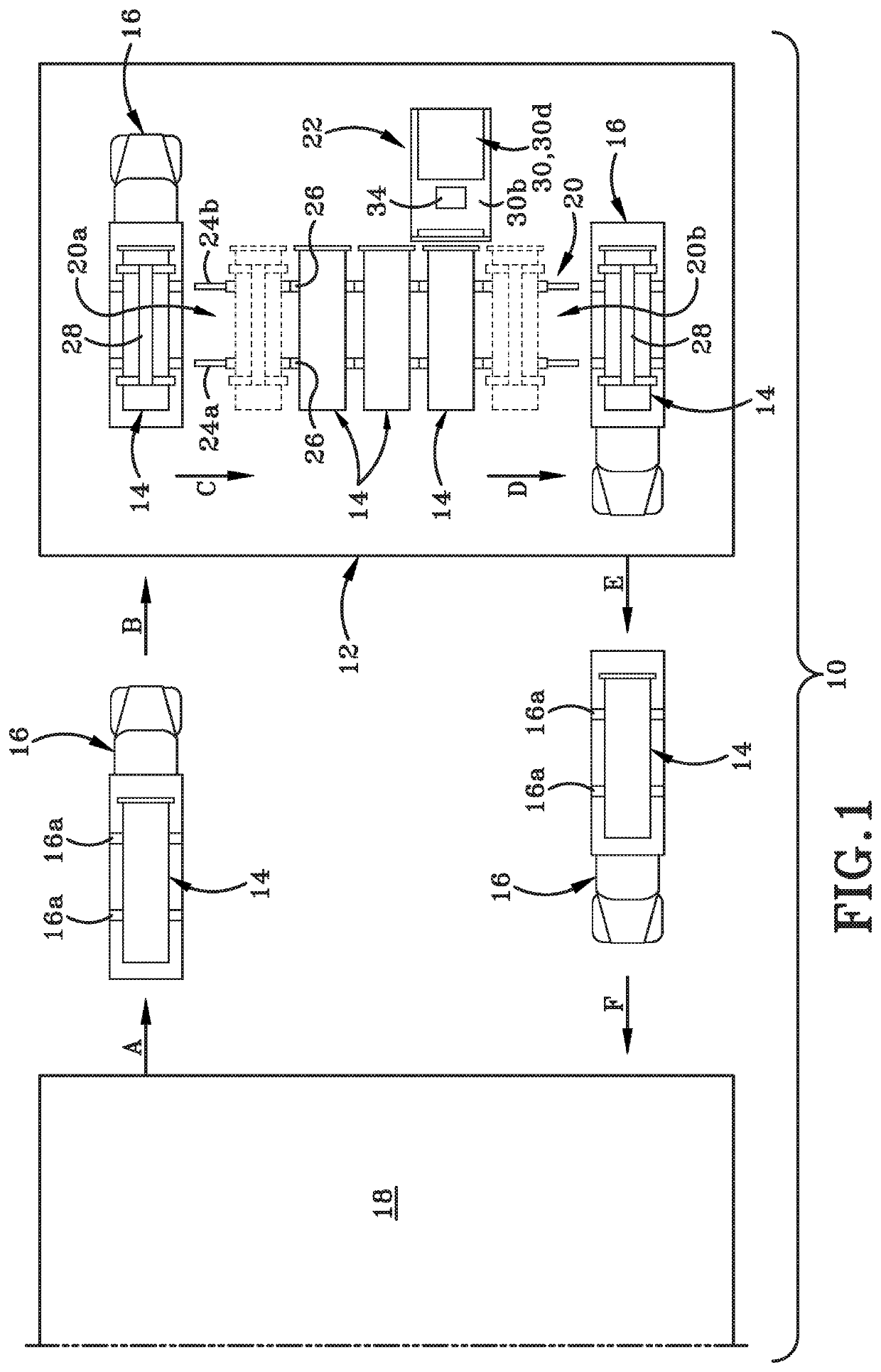
[0031]Referring to FIG. 1 there is shown a diagrammatic top plan view of a system, method, and apparatus in accordance with the present disclosure. The system, generally indicated at 10, includes a cleaning station 12 that is permanently set up for cleaning heat exchangers 14, at least one transportation device 16, and a plant 18 where the one or more heat exchangers 14 are typically used in a process of some type. For example, the plant 18 may be a chemical plant that utilizes heat exchangers 14 in a chemical process, and because of the chemical process in which the heat exchangers 14 are used, the tubes in the heat exchanger tubes may need to be cleaned frequently. For example, the tubes of the heat exchanger2 14 need to be cleaned frequently, e.g. every few days or every week or two.

[0032]Cleaning station 12 may be provided in the same facility as the plant 18. Alternatively, cleaning station 12 may be provided at another location that is not in the same facility as the plant 18 ...

second embodiment

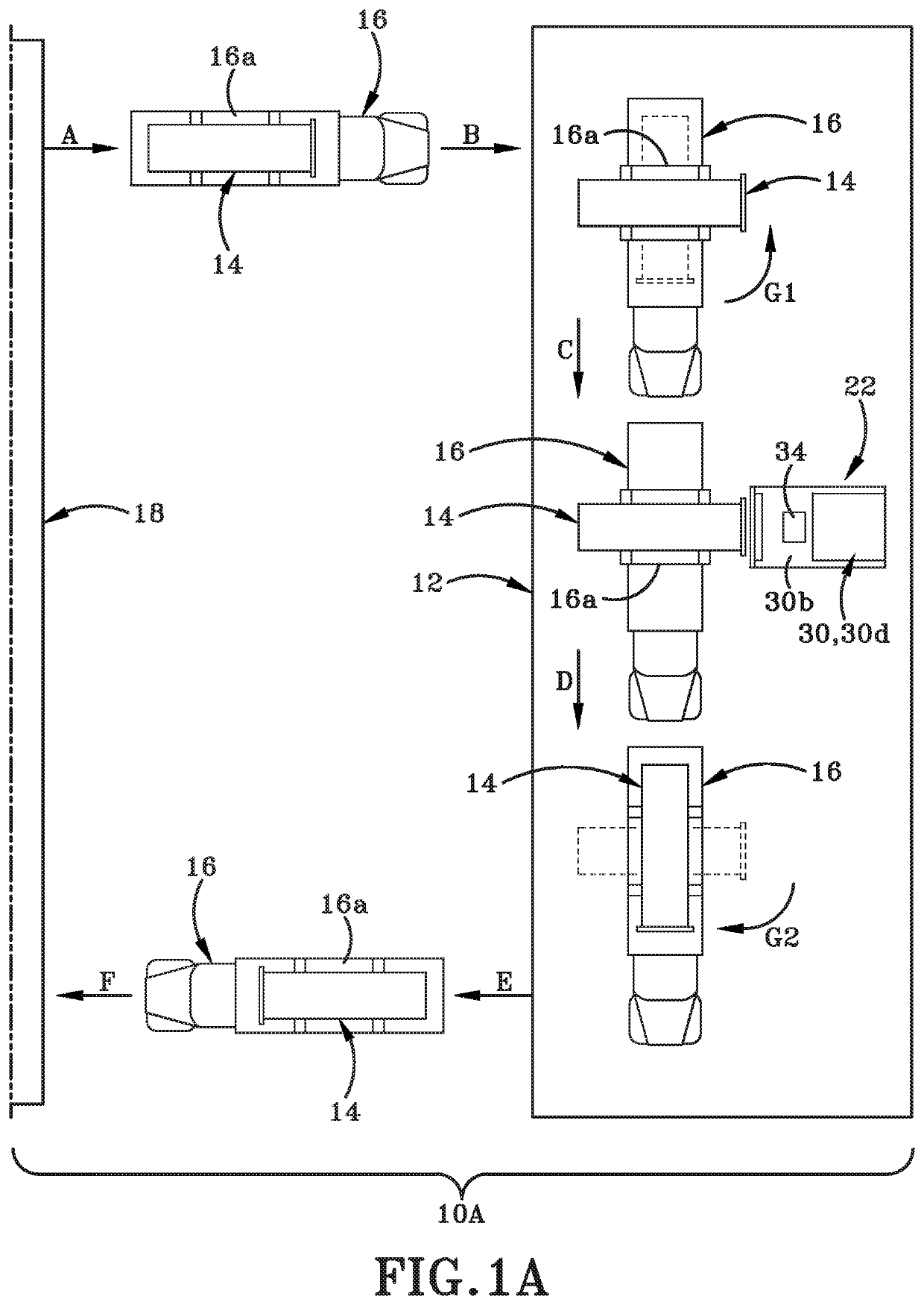
[0042]FIG. 1A shows a second embodiment system 10A where a different type of transportation device 16 is utilized and the translation assembly is omitted from the system. In this instance, the transportation device 16 is capable of extracting a dirty heat exchanger 14 (or tube bundle and end plate) from plant 18 (as shown by arrow “A”), the transportation device 16 moves toward the cleaning station as indicated by arrows “B” and “C” and is itself positioned at the cleaning position in front of cleaning apparatus 22. Before transportation device 16 reaches (or when it reaches) the cleaning position, transportation device 16 rotates heat exchanger 14 through 90° as indicated by arrow “G1” so that the heat exchanger is in the correct orientation to be cleaned by cleaning apparatus 22. After heat exchanger 14 is cleaned, the transportation device 16 rotates heat exchanger 14 through 90° once again so that heat exchanger 14 is aligned with a longitudinal axis of transportation device 16 ...

third embodiment

[0072]A movable platform 230j is provided between fixed platform 230b and base 230a. A mechanism 230k for raising or lowering movable platform 230j is provided on front and rear support assemblies 230g, 230g′. A third embodiment cleaning apparatus 242 is supported on movable platform 230j and by support assemblies 230g, 230g′. Platform 230j and support assemblies 230g, 230g′ correctly position water jet cleaning equipment 242 to perform a cleaning operation on a dirty heat exchanger 14 that is moved to the cleaning position in front of cleaning apparatus 222. Water jet cleaning equipment 242 includes multiple lances 246 that are positionable adjacent openings in the end plate of the heat exchanger 14 as has been previously described herein. A hose reel assembly 234 is operatively engaged with the water jet cleaning equipment 242 and with a remote cleaning fluid supply (not shown).

[0073]The water jet cleaning equipment 242 as illustrated in FIGS. 4A and 4B may be substantially simila...


PUM


Abstract

A system, apparatus and method of cleaning tubes of a heat exchanger or a tube bundle that includes disengaging the heat exchanger or bundle from a use-position in a process or a plant; moving the heat exchanger or bundle to a cleaning station remote from the use-position; positioning the heat exchanger or tube bundle in front of a cleaning apparatus; providing water jet cleaning equipment on the cleaning apparatus; responding to programming in a computing device and controlling the water jet cleaning equipment and a cleaning operation; providing a pattern of tube openings defined in an end plate of the heat exchanger or bundle to the computing device; actuating the water jet cleaning equipment with the computing device; and manually or automatically performing a cleaning operation with the water jet cleaning equipment under control of the programming of the computing device and by following the provided pattern of tube openings.

Description

CROSS-REFERENCE TO RELATED APPLICATIONS[0001]This is a Continuation-in-Part of U.S. patent application Ser. No. 16 / 942,945, filed Jul. 30, 2020 (entitled “ROTARY TOOL WITH SMART INDEXING”); which is a Continuation-in-Part of U.S. patent application Ser. No. 16 / 265,387 filed Feb. 1, 2019, now U.S. Pat. No. 10,747,238, which is a Continuation of U.S. patent application Ser. No. 16 / 155,340 filed Oct. 9, 2018, now U.S. Pat. No. 10,599,162; which is a Continuation of U.S. patent application Ser. No. 15 / 689,483 filed Aug. 29, 2017, now U.S. Pat. No. 10,401,878; which claims the benefit of U.S. Provisional Patent Application Ser. No. 62 / 381,390, filed Aug. 30, 2016.[0002]U.S. patent application Ser. No. 16 / 155,340 filed Oct. 9, 2018, now U.S. Pat. No. 10,599,162, is a Continuation of U.S. patent application Ser. No. 15 / 689,572, filed Aug. 29, 2017, now U.S. Pat. No. 10,408,552, which claims the benefit of U.S. Provisional Patent Application Ser. No. 62 / 381,390, filed Aug. 30, 2016.[0003]U....

Claims


Application Information

Patent Timeline
IPC IPC(8): G05D7/06B24C7/00G06F3/0488B24C3/32F28G1/16F28G15/00F28G15/02F28G15/08
CPCG05D7/0617B24C7/0015G06F3/04886B24C3/327F28D7/16F28G15/003F28G15/02F28G15/08F28G1/163
Inventor GROMES, SR., TERRY D.GROMES, JR., TERRY D.GRIFFIN, KRISTEN E.SHOCKEY, JR., JON M.EAST, GORDON W.JACKSON, WILLIAM C.
Owner TERYDON
Why Eureka
Try Eureka