Turbine housing for gas turbochargers

a technology of turbocharger and turbine housing, which is applied in the direction of liquid fuel engines, motors, mechanical devices, etc., can solve the problems of not addressing thermal stress problems, turbochargers are subjected to significant mechanical stresses, and the exhaust system itself affecting fuel consumption, etc., to achieve maximum sealing effect and thin materials

Inactive Publication Date: 2010-12-16
BENTELER AUTOMOBILTECHNIK GMBH
View PDF7 Cites 28 Cited by
  • Summary
  • Abstract
  • Description
  • Claims
  • Application Information

AI Technical Summary

Benefits of technology

[0005]Hence, an object of the present invention is to provide a turbine housing for an exhaust turbocharger which compensates for temperature expansion between the rotor housing and the exhaust gas outlet, has maximum sealing effect for the internal system, while at the same time uses very thin materials, and avoids welding in the sensitive outlet area of the rotor housing.

Problems solved by technology

However, the weight of the exhaust system itself also affects fuel consumption.
This need for a lightweight construction conflicts with the fact that when in use, turbochargers are subjected to significant mechanical stresses and especially extremely high thermal loads that demand a robust construction.
Thus, appropriate thermal compensating elements must be provided, although the same often have leaks.
The arrangement depicted in DE 100 22 052 A1 makes it possible to connect the internal system to the external system in a sealed manner, but it does not address the thermal stress problems that occur, except by deforming the components.
This results in the risk that the internal system or the rotor housing will collide with the turbine rotor.
DE 10352960 A1 indicates how the expansion can be compensated, but economic fabrication of the subject housing may be jeopardized by the thermomechanical loads that occur as result of this construction, by the required material properties, and by the production tolerances required for smooth operation.

Method used


Image

  • Turbine housing for gas turbochargers
  • Turbine housing for gas turbochargers

Examples


Embodiment Construction

[0022]For purposes of description herein, the terms “upper,”“lower,”“right,”“left,”“rear,”“front,”“vertical,”“horizontal,” and derivatives thereof shall relate to the invention as oriented in FIG. 1. However, it is to be understood that the invention may assume various alternative orientations and step sequences, except where expressly specified to the contrary. It is also to be understood that the specific devices and processes illustrated in the attached drawings, and described in the following specification are simply exemplary embodiments of the inventive concepts defined in the appended claims. Hence, specific dimensions and other physical characteristics relating to the embodiments disclosed herein are not to be considered as limiting, unless the claims expressly state otherwise.

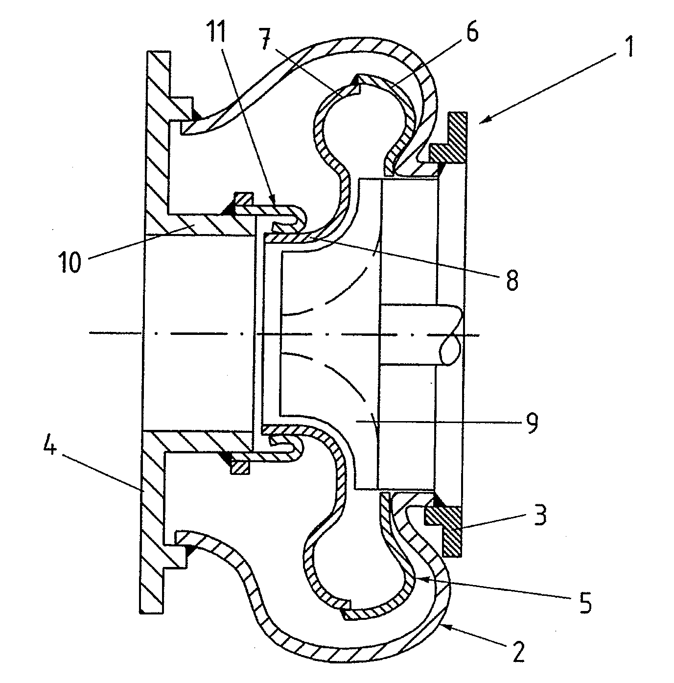
[0023]FIG. 1 depicts a turbine housing 1 for an exhaust gas turbocharger. The turbine housing 1 includes an external housing 2 that extends from a housing flange 3 to an outlet flange 4. The external h...


PUM


Abstract

A turbine housing for exhaust gas turbochargers includes an outlet pipe and an external housing connected therewith. A rotor housing is disposed in the external housing and has a pipe-shaped neck operably coupled with the outlet pipe and axially displaceable relative to the same. A separate sealing ring is positioned operably between the neck and the outlet pipe, supported by the outlet pipe, and has an inwardly turned sealing portion sealingly and slidingly engaging the neck to form a secure gas seal therebetween.

Description

CLAIM OF PRIORITY[0001]Applicants hereby claim the priority benefits under the provisions of 35 U.S.C. §119, basing said claim of priority on German Patent Application Serial No. 10 2009025054.9, filed Jun. 10, 2009. In accordance with the provisions of 35 U.S.C. §119 and Rule 55(b), a certified copy of the above-listed German patent application will be filed before grant of a patent.BACKGROUND OF THE INVENTION[0002]The present invention relates to a turbine housing for exhaust gas turbochargers and the like.[0003]Internal combustion engines for motor vehicles are increasingly charged by turbochargers in order to reduce fuel consumption. However, the weight of the exhaust system itself also affects fuel consumption. Turbochargers should therefore be as lightweight as possible. This need for a lightweight construction conflicts with the fact that when in use, turbochargers are subjected to significant mechanical stresses and especially extremely high thermal loads that demand a robus...

Claims


Application Information

Patent Timeline
Patent Type & Authority Applications(United States)
IPC IPC(8): F04D29/10
CPCF01D25/26F02B37/00F02C6/12F05D2220/40F05D2240/14
Inventor GRU MANN, ELMARSMATLOCH, CHRISTIAN
Owner BENTELER AUTOMOBILTECHNIK GMBH
Why Eureka
Try Eureka