Flexible rod assembly for spinal fixation

a flexible rod and spinal fixation technology, applied in the field of flexible rod assemblies, can solve the problems of not allowing virtually any bending of the spine, not allowing axial stretch along the rod axis, and prior art arrangements that exhibit significant limitations in being able to provide stabilization of the spine, and achieve the effect of stabilizing the spine of a patien

Inactive Publication Date: 2010-12-16
S S WHITE TECH
View PDF53 Cites 29 Cited by
  • Summary
  • Abstract
  • Description
  • Claims
  • Application Information

AI Technical Summary

Benefits of technology

[0010]This bendably resilient flexible spinal fixation rod is intended for dynamic stabilization of the spine. According to a preferred embodiment of the invention a flexible spinal fixation rod and spring combination that provides relatively stiff bending compliance has couplings at both ends, one of which couplings (the floating coupling) allows the spring to extend independently of the rod. Each coupling is adapted to be attached to a pedicle screw, with the screws being connected to corresponding vertebrae so as to span two or more vertebrae and allow limited extension axially when the spine is bent. This is important because as the spine bends, it bends around the central axis of the spine, and the spine rod is attached several inches from that axis, so that the arc length of the rod and spring combination must increase as the spine's radius of bending decreases. Due to the spring-like characteristics of the flexible spine fixation rod assembly, it returns to its original configuration so as to help maintain the shape and axial position of the corresponding portion of the spine and provides axial compressive strength to the spine.

Problems solved by technology

One of the main drawbacks to using such rigid metal rods is that they do not allow virtually any bending of the spine and they do not allow axial stretch along the rod axis.
However, all such prior art arrangements exhibit significant limitations in being able to provide stabilization of the spine while approximating the everyday natural flexion of the spine.

Method used


Image

  • Flexible rod assembly for spinal fixation
  • Flexible rod assembly for spinal fixation
  • Flexible rod assembly for spinal fixation

Examples


first embodiment

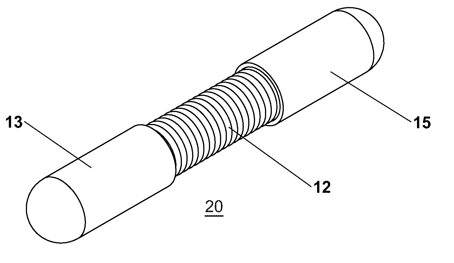
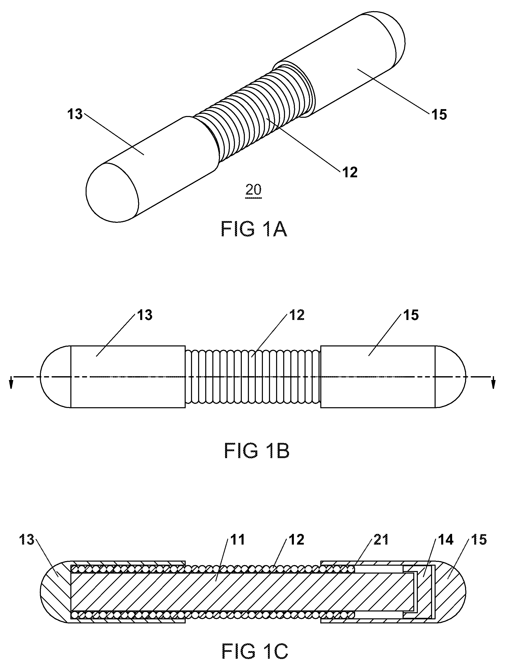
[0038]A first embodiment is shown in FIGS. 1a through 1c, in which a flexible spinal fixation bendably resilient rod assembly 20 is adapted to span a single spinal disc and to be fastened at each end to an adjacent vertebra via pedicle screws.

[0039]The various rod assembly embodiments described herein are bendably resilient. That is, they resiliently resist bending from their original configurations and return to those original configurations when the bending stress applied to them is relaxed.

[0040]The assembly 20 consists of a single length (unitary) flexible inner core rod 11 slidably and coaxially disposed within an outer cylindrical spring 12. A fixed end coupling 13 is positioned over the core 11 and overlaps the adjacent end of spring 12 in such a way as to effectively secure the fixed end coupling 13, adjacent end of core 11, and adjacent end of spring 12 together.

[0041]An optional end stop 14 is affixed to the opposite end of core rod 11 to provide a limit to axial travel or...

second embodiment

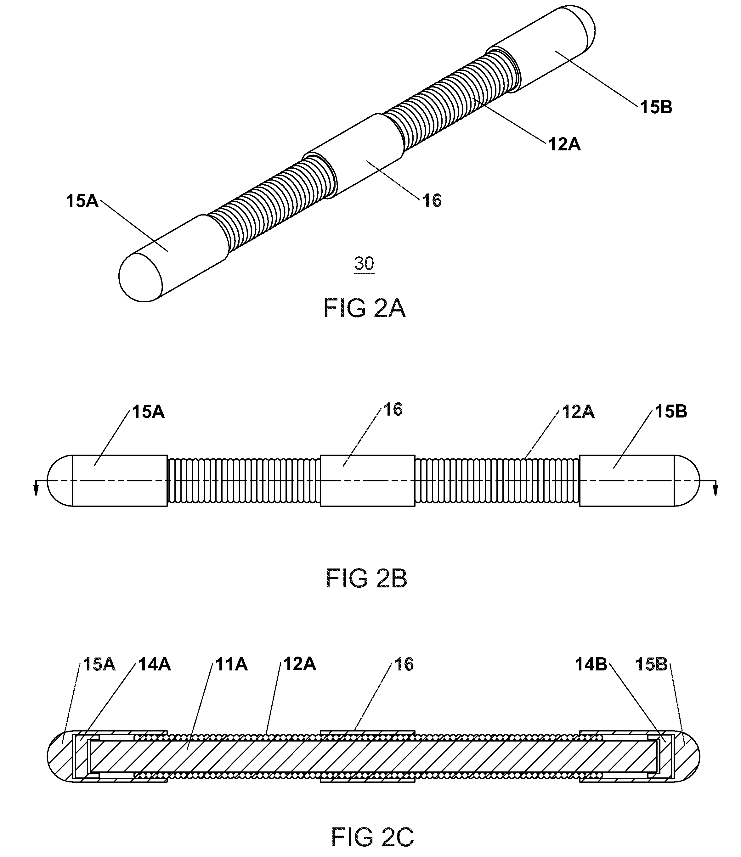
[0043]A second embodiment is shown in FIGS. 2a through 2c which shows a rod assembly 30 designed to span three vertebrae (two disc spaces). Its construction and operation is similar to the first embodiment illustrated in FIGS. 1a through 1c, having an inner core rod 11A as described above, but with sliding or floating end couplings 15A and 15B at each end. At the center of the assembly 30 is a fixed coupling 16 which is secured to the adjacent central portions of both the core 11A and spring 12A. The central coupling 16 also provides a clamping location for a middle pedicle screw.

third embodiment

[0044]A third embodiment is shown in FIGS. 3a through 3c. The rod assembly 40 is designed to span a single spinal disc space (two vertebrae) and has a construction similar to that of the assembly 20. The assembly 40 includes a fixed end coupling 13A, which is substantially longer than the opposite floating end coupling 15C, for rigid fixation of adjacent spinal discs and vertebrae. The longer fixed end coupling 13A is (except for length) similar to the fixed end coupling 13 shown in FIGS. 1a through 1c, and also serves a purpose similar to that of the fixed center coupling 16 shown in FIGS. 2a through 2c. This third embodiment is suitable for use in patients who have vertebrae which were fused in previous surgery.


PUM


Abstract

A flexible spinal fixation rod assembly that provides relatively stiff bending compliance provided by a core rod or tube that is connected to surrounding spring and associated couplings in such a way that when the core rod is bent, the spring extends and the associated couplings move away from each other, with the core rod generating a force tending to return the core rod to its unbent configuration thereof and the spring generating a force tending to return the couplings to there unextended configuration thereof. Couplings connect each end of the rod or tube to corresponding pedicle screws for attachment to corresponding vertebrae. As the spine bends, this arrangement allows the spine to bend against limited resistance, exhibiting the necessary axial and compressive strength, and applies force to return the spine to its original configuration.

Description

CROSS-REFERENCE TO RELATED APPLICATION[0001]This application claims the benefit of U.S. Provisional Application Ser. No. 61 / 014,027 filed Dec. 15, 2007 and entitled Flexible Shaft For Spinal Fixation.BACKGROUND OF THE INVENTION[0002]The present invention relates to a flexible rod assembly for stabilizing the spine while allowing the spine to bend.[0003]For cases of congenital spinal defects (such as scoliosis), degenerative disc disease and spinal trauma, surgical intervention is typically required to stabilize and support the spine and eliminate pain. Such stabilization has traditionally been provided by rigid metal rods positioned along the posterior side of the spine, fabricated from stainless steel or titanium to support, strengthen, and / or straighten the spine. These stabilizing rods are firmly attached to pedicle screws which are fastened to adjacent vertebrae.[0004]Spinal support is required to prevent undue stress on the discs on either side of the vertebrae that are connect...

Claims


Application Information

Patent Timeline
Patent Type & Authority Applications(United States)
IPC IPC(8): A61B17/70
CPCA61B17/7028A61B17/702
Inventor PARLATO, BRIAN D.SPIVAK, JEFFREY MICHAELUMBACH, BRIAN
Owner S S WHITE TECH
Why Eureka
Try Eureka