Techniques for building an aggregate model for performing diagnostics

a diagnostic model and aggregate technology, applied in the field of diagnostics, can solve the problems of difficult task to determine a set, inability to readily obtain full failure data, and inability to establish the de facto tool of problem diagnosis by experts

Active Publication Date: 2010-12-16
ORACLE INT CORP
View PDF99 Cites 36 Cited by
  • Summary
  • Abstract
  • Description
  • Claims
  • Application Information

AI Technical Summary

Benefits of technology

[0012]The foregoing, together with other features and embodiments will become more app

Problems solved by technology

Expert systems have not been successful in establishing themselves as the de facto tool for problem diagnosis.
It may be a challenging task to determine a set of rules to correctly identify problems in a generic environment that applies to all user systems.
Further, full failure data may not be readily available for problem diagnosis, resulting more often than not in failed rule assertions.
With only partially captured failure data, it is often difficult to identify an appropriate set of rules that can correctly identify the cause of a problem.
These problems are also not solved by knowledge forums and self-service knowledge bases.
The ineffectiveness of expert systems for problem diagnosis gives rise to problem diagnostic solutions using knowledge bases for user self-services or to onl

Method used


Image

  • Techniques for building an aggregate model for performing diagnostics
  • Techniques for building an aggregate model for performing diagnostics
  • Techniques for building an aggregate model for performing diagnostics

Examples


Embodiment Construction

[0028]In the following description, for the purposes of explanation, specific details are set forth in order to provide a thorough understanding of embodiments of the invention. However, it will be apparent that the invention may be practiced without these specific details.

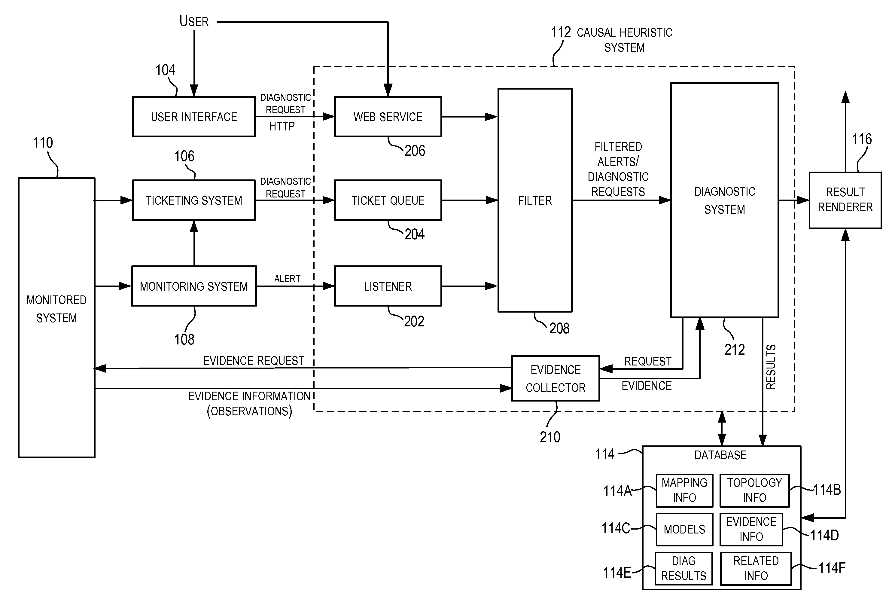
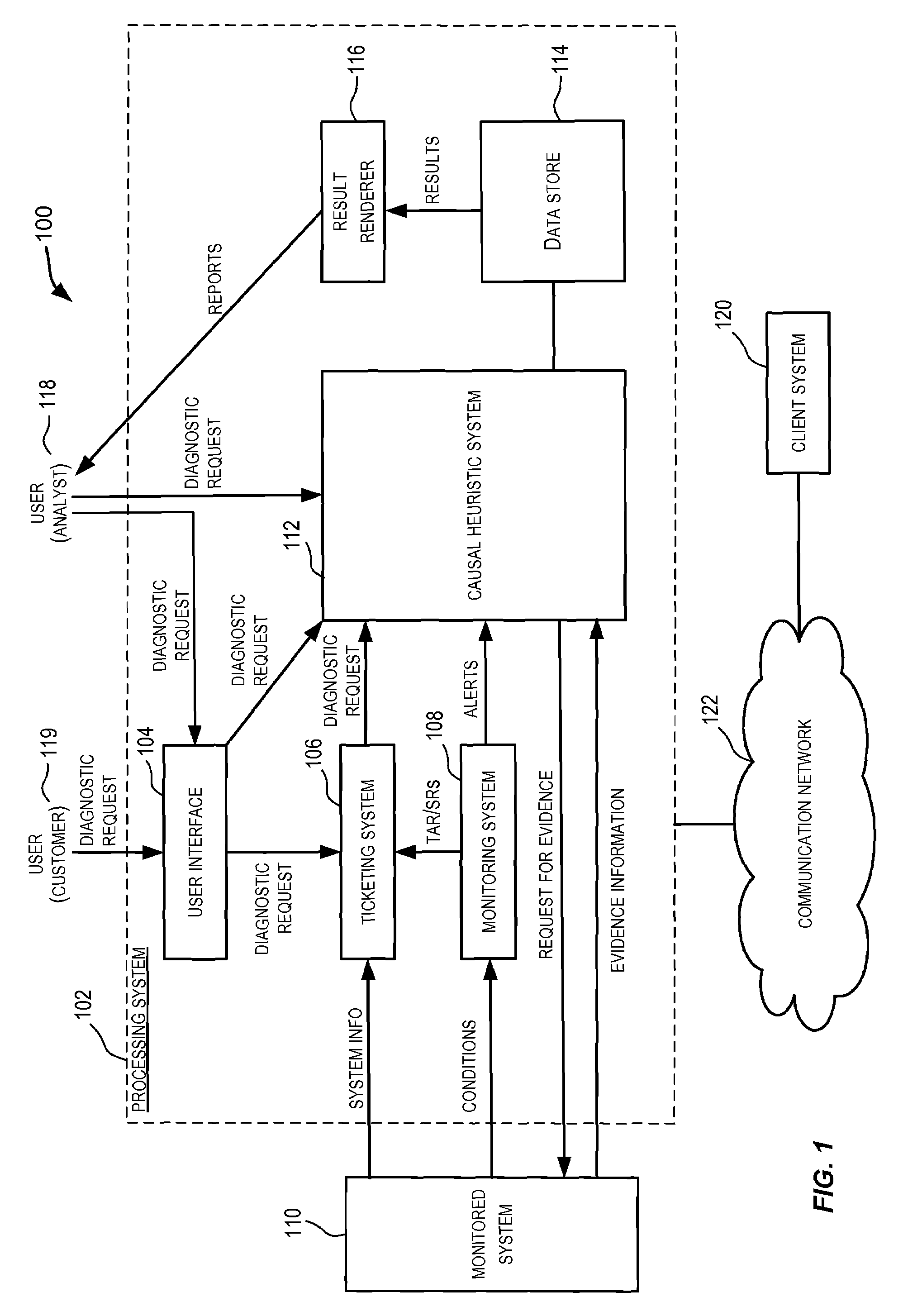
[0029]FIG. 1 is a simplified block diagram of a system 100 incorporating an embodiment of the present invention. As depicted in FIG. 1, system 100 comprises a processing system 102 that is configured to provide diagnostic services for one or more systems 110 (referred to as monitored systems). A monitored system 110 may be a software system, a hardware system, an enterprise system, and the like, or combinations thereof. For example, monitored system 110 may be a complex enterprise software system such as a database system and related products provided by Oracle Corporation™ of California. Monitored system 110 may comprise one or more systems (e.g., may be an eco-system of multiple systems) with each system running...


PUM


Abstract

Techniques for building a model for performing diagnostics. In one embodiment, a set of models is determined based upon a topological relationship created upon receiving an alert or a request for which diagnostics are to be performed. An aggregate model is then generated based upon the set of models and the topological relationship. The aggregate model is then used for performing the diagnostics.

Description

CROSS-REFERENCES TO RELATED APPLICATIONS[0001]The present application incorporates by reference for all purposes the entire contents of the following related applications filed concurrently with the present application:[0002](1) U.S. application Ser. No. ______, entitled TECHNIQUES FOR DETERMINING MODELS FOR PERFORMING DIAGNOSTICS (Attorney Docket No.: 021756-061400US); and[0003](2) U.S. application Ser. No. ______, entitled TECHNIQUES FOR GATHERING EVIDENCE FOR PERFORMING DIAGNOSTICS (Attorney Docket No.: 021756-075500US).BACKGROUND OF THE INVENTION[0004]Embodiments of the present invention relate to diagnostics, and more specifically to techniques for building an aggregate diagnostic model based upon a set of models determined from a topological relationship between systems and applications.[0005]Various conventional techniques exist in the industry today to perform problem diagnosis. These various techniques may range from expert systems at one end of the spectrum for diagnosabil...

Claims


Application Information

Patent Timeline
IPC IPC(8): G06F11/28
CPCG05B23/0243G06F11/079H04L41/0631H04L41/0604G06F11/2257
Inventor BEG, MIRZA MOHSINSUM, CHARLES P.
Owner ORACLE INT CORP
Why Eureka
Try Eureka